
Automatic simple portal crane and application method thereof

A simple, gantry technology, applied in the direction of cranes, traveling mechanisms, trolley cranes, etc., can solve the problems of high manpower and material resources for lifting and transporting gantry cranes, inability to achieve up and down lifting or folding, and inability to pass through, so as to facilitate transportation. Goods, saving manpower and material resources, and improving work efficiency

Pending Publication Date: 2020-04-17
泉州市苏合建桥设备有限公司
View PDF0 Cites 2 Cited by
  • Summary
  • Abstract
  • Description
  • Claims
  • Application Information

AI Technical Summary

Problems solved by technology

[0003] In the prior art, after the hoisting of the simple transport door crane is completed, the equipment is loaded into the vehicle. Since the existing transport door machines are fixed, they cannot be lifted up and down or folded. The high transport door machine will cause the transport vehicle to be too high when passing through the tunnel and cannot pass through, resulting in the need to disassemble it after use and reinstall it when using it, which is very inconvenient, and when lifting the transport door machine It needs a lot of manpower and material resources, and because the door machine is high, it is not easy to lift

Method used


Image

  • Automatic simple portal crane and application method thereof
  • Automatic simple portal crane and application method thereof
  • Automatic simple portal crane and application method thereof

Examples


Embodiment Construction

[0025] The present invention will be further described below in conjunction with the accompanying drawings.

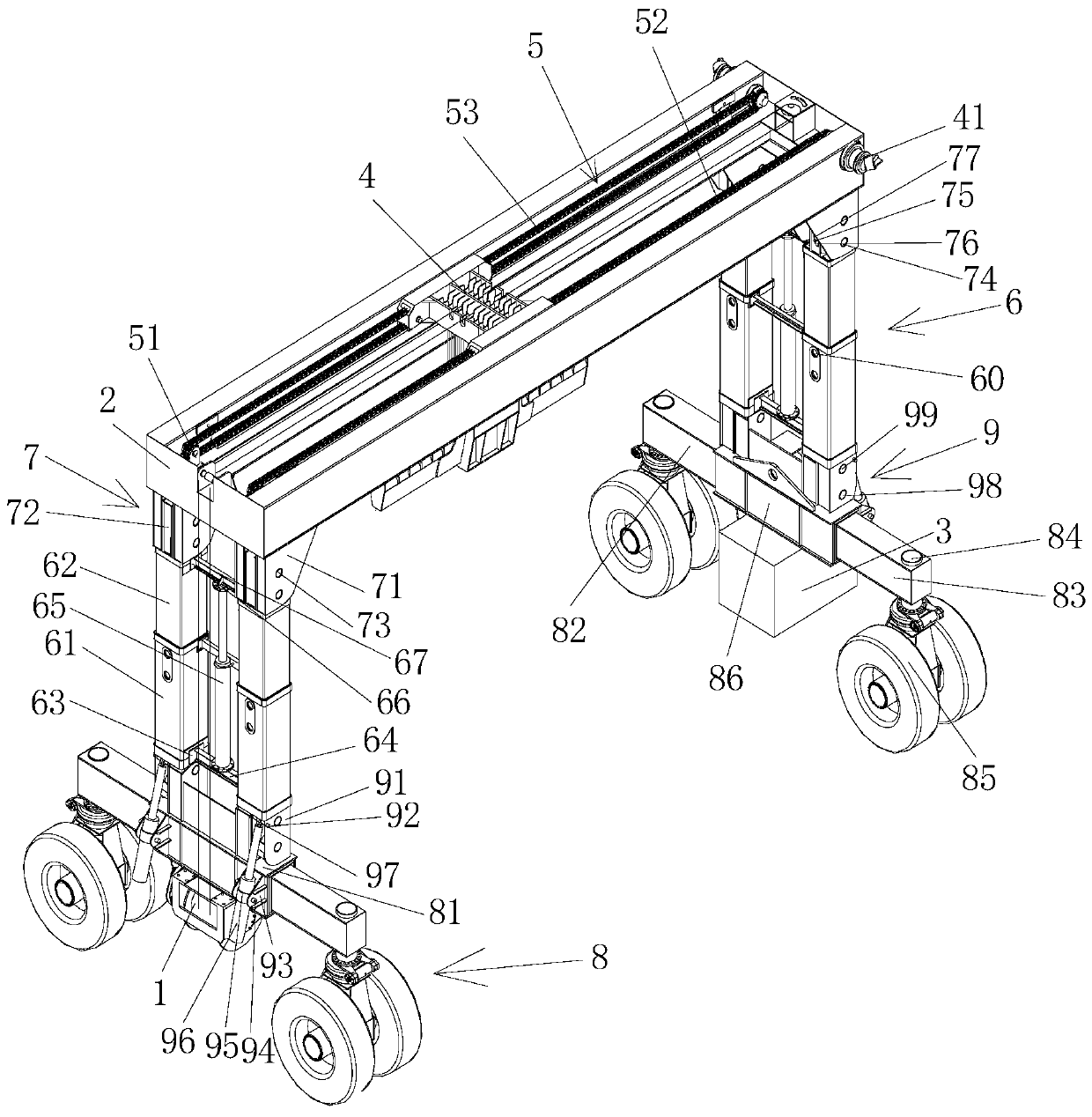
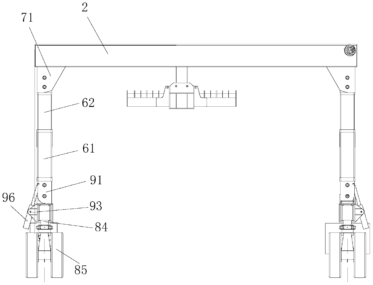
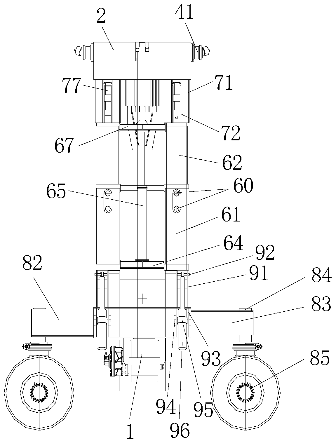
[0026] see Figure 1 to Figure 5 As shown, the present invention provides an embodiment: an automatic simple door machine, including a hydraulic winch 1, a girder assembly 2, a hydraulic tank 3, a crown block 4, and a crown block traverse motor 41, and the girder assembly 2 front and rear The right end of the surface is provided with the crane traversing motor 41, the crane 4 is erected between the front and rear crossbars in the girder assembly 2, and the crossbar is arranged between the front and rear crossbars of the girder assembly 2. The crane traversing motor 41 drives the moving mechanism 5 for the crane to move left and right; the left and right ends of the lower surface of the girder assembly 2 are provided with a telescopic mechanism 6 for supporting the girder assembly 2, and the telescopic mechanism 6 A first folding mechanism 7 for folding the equipment i...


PUM


Abstract

The invention provides an automatic simple portal crane and an application method thereof. The automatic simple portal crane comprises a hydraulic winch, a large beam assembly, a hydraulic box, a crown block and crown block translation motors; crown block translation motors are arranged at the right ends of the front and back surfaces of the large beam assembly; the crown block is erected betweenfront and back cross bars in the large beam assembly; a moving mechanism for driving the crown block to move left and right by the crown block translation motors is arranged between the front and backcross bars of the large beam assembly; extension mechanisms for supporting the large beam assembly are arranged at the left and right ends of the lower surface of the large beam assembly; first folding mechanisms for folding equipment are arranged between the extension mechanisms and the large beam assembly; walking mechanisms for driving the single portal crane to move are arranged under the extension mechanisms; and second folding mechanisms for folding the walking mechanisms are arranged under the walking mechanisms. The automatic simple portal crane is simple structure and convenient to operate, can realize lifting and folding thereof, and is free of disassembly and convenient to transport.

Description

technical field [0001] The invention relates to the technical field of bridge engineering, in particular to an automatic simple door operator and its usage method. Background technique [0002] The current simple transport door crane is equipped with a high-power engine. All mechanism movements are driven by hydraulic pressure and operated by wireless remote control. The main mechanism is composed of three parts: lifting mechanism, trolley running mechanism and cart running mechanism. The usual normal work operation steps are at first the lifting action, the control starts the starting mechanism, and the empty hook is lowered to a suitable position. Then the hoisting device raises the item to a suitable height, and then it is necessary to drive the trolley running mechanism and the cart running mechanism to the predetermined position before stopping. Then start the hoisting mechanism again to lower the object, and then raise the empty hook to a suitable height, control the ...

Claims


Application Information

Patent Timeline
Patent Type & Authority Applications(China)
IPC IPC(8): B66C19/00B66C5/04B66C9/14
CPCB66C5/04B66C9/14B66C19/00
Inventor 张冲颜朝友苏孝局丁程苏翔
Owner 泉州市苏合建桥设备有限公司
Learn More