Dyeing machine cloth lifting device with adjustable traction

A dyeing machine and traction technology, applied in the direction of processing textile material drums and textile material carriers, etc., can solve the problems of insufficient traction, reducing the dyeing efficiency of fabrics, slippage between the cloth lifting roller and the fabric, etc., to achieve a simple adjustment method and improve dyeing efficiency. Effect

Active Publication Date: 2020-04-17
ZHEJIANG TWIN LANTERN HOME TEXTILE
View PDF7 Cites 0 Cited by
  • Summary
  • Abstract
  • Description
  • Claims
  • Application Information

AI Technical Summary

Problems solved by technology

However, the traction force of the existing cloth lifting device for cloth dyeing is often insufficient, resulting

Method used


Image

  • Dyeing machine cloth lifting device with adjustable traction
  • Dyeing machine cloth lifting device with adjustable traction
  • Dyeing machine cloth lifting device with adjustable traction

Examples


Example Embodiment

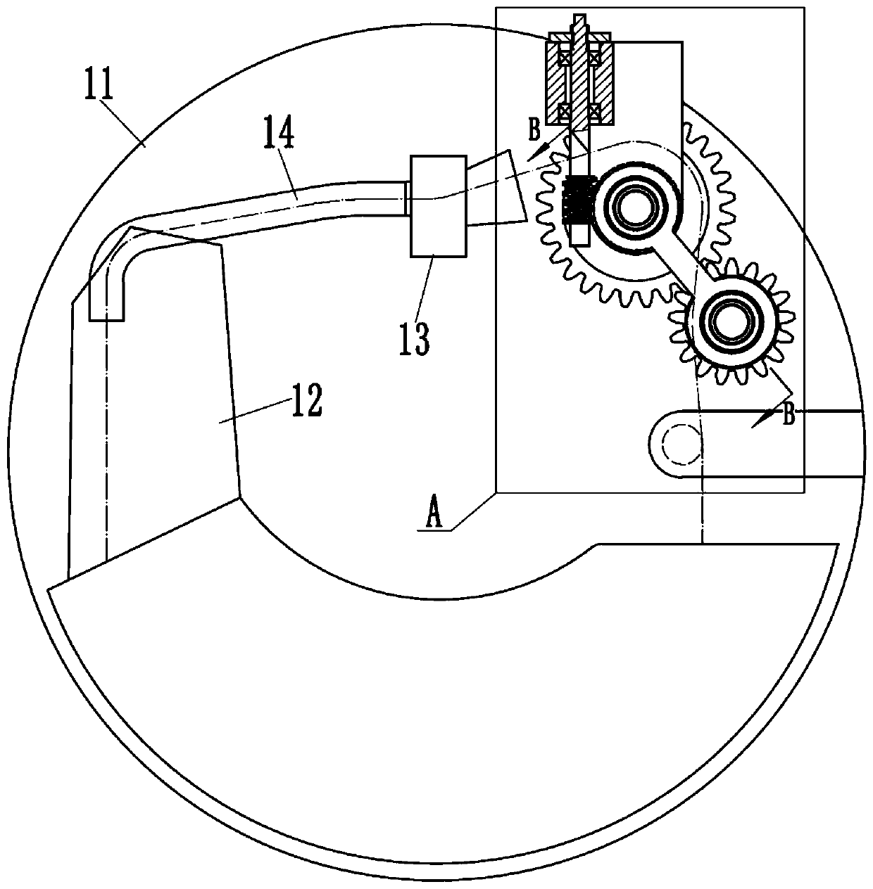
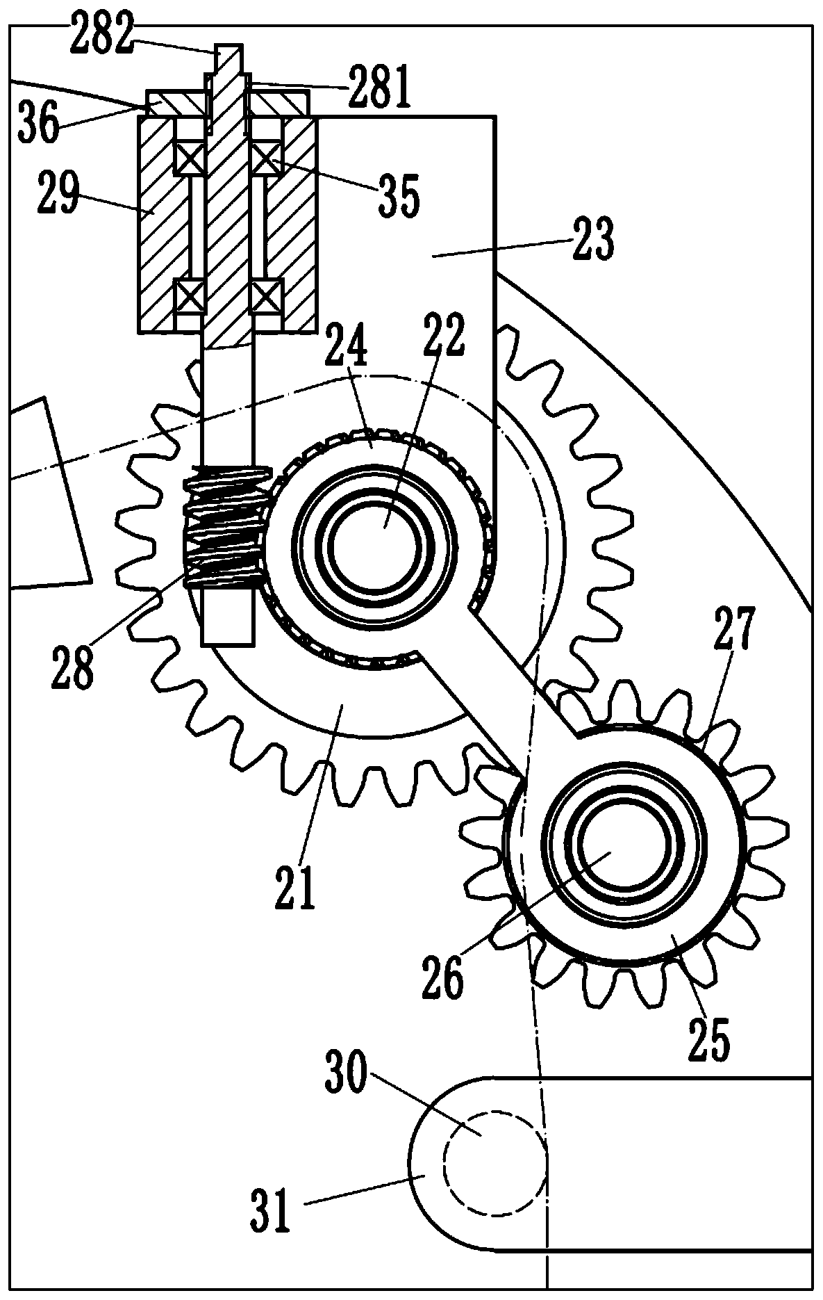
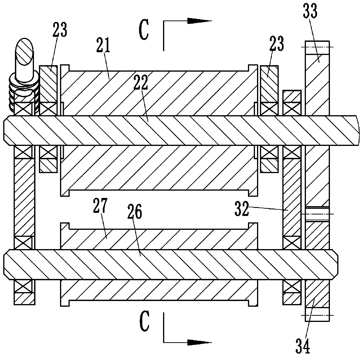
[0018] Examples, see as Figure 1 to Figure 4 As shown, a cloth lifting device of a dyeing machine with adjustable traction force includes a cylinder body 11 of the dyeing machine, a cloth lifting device arranged in the cylinder body 11, a dyeing nozzle assembly 13, a cloth guide pipe 14 and a cloth storage tank 12, The dyeing nozzle assembly 13 is arranged on the upper end of the cloth guide pipe 14, and the cloth storage groove 12 is connected with the lower end of the cloth guide pipe 14; The cloth lifting roller 21 is fixed in the middle of the support shaft 22, the front and rear ends of the support shaft 22 are hinged on a corresponding connecting plate 23, the connecting plate 23 is fixedly connected with the cylinder 11, and the support shaft 22 passes through the front side. The extension end of the connecting plate 23 is hinged with a worm wheel 24, the outer wall of the worm wheel 24 is fixed with a hinge arm 25, the lower end of the hinge arm 25 is hinged with an a...


PUM


Abstract

The invention discloses a dyeing machine cloth lifting device with adjustable traction. The dyeing machine cloth lifting device includes a cylinder body of a dyeing machine and a cloth lifting devicebody; the cloth lifting device body includes a cloth lifting roller arranged on the right side of a dyeing nozzle assembly, and the cloth lifting roller is fixed to the middle part of a supporting shaft, the supporting shaft is hinged to a connecting plate, and the connecting plate is fixedly connected to the cylinder body; a worm gear is hinged to the supporting shaft, a hinge arm is fixed to theouter wall of the worm gear, an adjusting shaft is hinged to the lower end of the hinge arm, and adjusting rollers are fixed to the adjusting shaft; the worm wheel meshes with a worm, the upper end of the worm extends out of the cylinder body, and limiting rollers are arranged below the adjusting roller; and the limiting roller is fixed on the inner wall of the cylinder body through a supportingplate. A wrap angle of a fabric to the cloth lifting roller is changed by changing the position between the adjusting rollers, so that the traction of the cloth lifting roller to the fabric is changed, the adjustment method is simple and fast, and the dyeing machine cloth lifting device can be applied to different fabrics, and the dyeing efficiency can be effectively improved.

Description

technical field [0001] The invention relates to the technical field of textile dyeing and finishing machinery, in particular to a cloth lifting device for a dyeing machine with adjustable traction. Background technique [0002] The dyeing machine is used for dyeing, bleaching, scouring and washing of wool sweaters, acrylic and cotton sweaters, etc. It can also be used for bleaching and dyeing of gloves, socks, towels and other finished products. It is a kind of finished product suitable for a wide range. The ideal bleaching and dyeing equipment, in the continuous production of textile finishing, because the textile fabric needs to be unrolled under the traction of the cloth lifting device when passively unwinding, and during continuous production, high-speed cloth lifting is required. However, the traction force of the existing cloth lifting device for fabric dyeing is often insufficient, which causes slippage between the cloth lifting roller and the fabric, thereby reducing...

Claims


Application Information

Patent Timeline
IPC IPC(8): D06B23/02D06B23/04
CPCD06B23/02D06B23/04
Inventor 高志英
Owner ZHEJIANG TWIN LANTERN HOME TEXTILE
Why Eureka
Try Eureka