Double-stage traveling wave thermo-acoustic engine system

A thermoacoustic engine and traveling wave technology, applied in the direction of machines/engines, mechanisms that generate mechanical power, mechanical equipment, etc., can solve problems such as reducing the temperature difference between vibrations and lack of acoustic impedance matching methods

Inactive Publication Date: 2020-04-17
NORTHEAST DIANLI UNIVERSITY
View PDF7 Cites 0 Cited by
  • Summary
  • Abstract
  • Description
  • Claims
  • Application Information

AI Technical Summary

Problems solved by technology

For two-stage thermoacoustic engines and multi-stage loop thermoacoustic engines without symmetrical structures, there is still a lack of methods to achieve acoustic impedance matching, reduce the temperature difference between vibrations, and realize the utilization of low-grade heat sources.

Method used


Image

  • Double-stage traveling wave thermo-acoustic engine system
  • Double-stage traveling wave thermo-acoustic engine system
  • Double-stage traveling wave thermo-acoustic engine system

Examples


Embodiment Construction

[0019] The present invention will be described in further detail below in conjunction with the accompanying drawings and specific embodiments. The specific embodiments described here are only used to explain the present invention, and are not intended to limit the present invention.

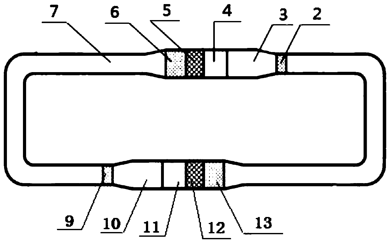
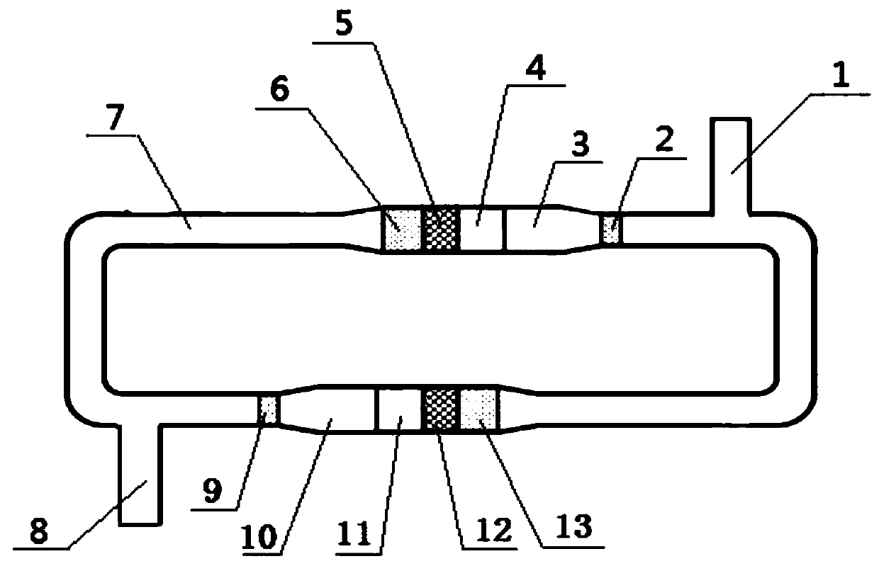
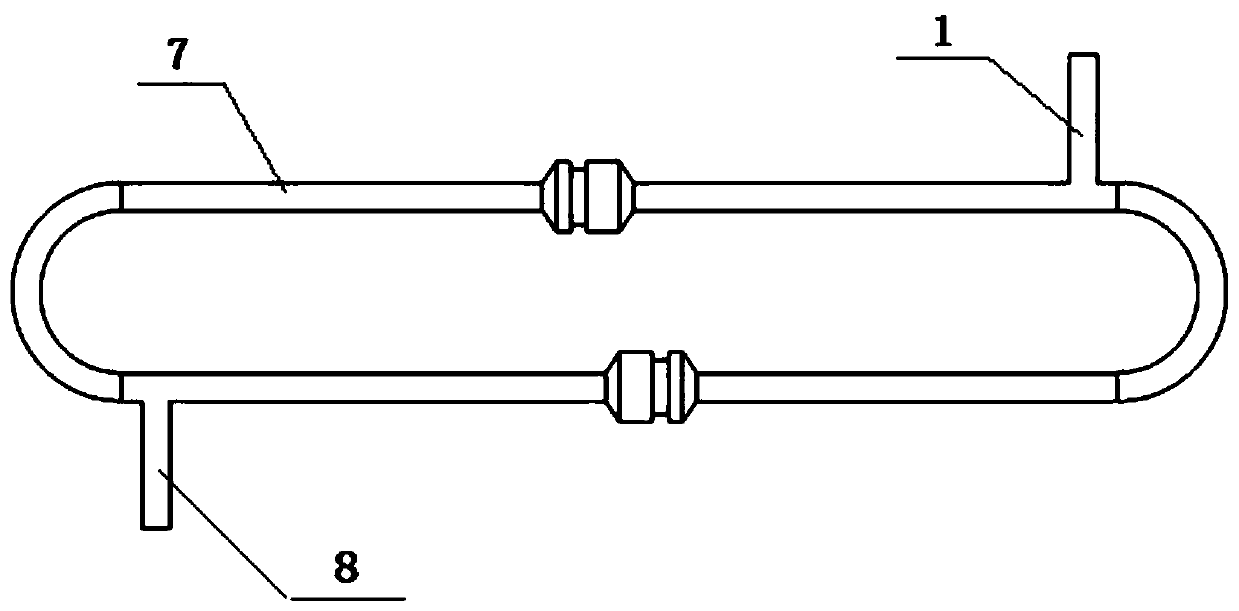
[0020] Refer to attached figure 2 As shown, a two-stage traveling wave thermoacoustic engine system includes: a first bypass pipe 1, a first room temperature cold end heat exchanger 2, a first thermal buffer pipe 3, a first hot end heat exchanger 4, The first regenerator 5, the first cold end heat exchanger 6, the main resonance tube 7, the second side branch pipe 8, the second room temperature cold end heat exchanger 9, the second heat buffer pipe 10, the second hot end exchanger Heater 11, second regenerator 12, second cold end heat exchanger 13, main resonant tube 7 between the first room temperature cold end heat exchanger 2 and the second cold end heat exchanger 13 On the pipeline, the fir...


PUM

PropertyMeasurementUnit
Radiusaaaaaaaaaa
Lengthaaaaaaaaaa

Abstract

The invention provides a double-stage traveling wave thermo-acoustic engine system which comprises a first side branch pipe, a first-time room-temperature cold end heat exchanger, a first heat buffering pipe, a first hot end heat exchanger, a first heat return device, a first cold end heat exchanger, a main resonant pipe, a second side branch pipe, a second-time room-temperature cold end heat exchanger, a second heat buffering pipe, a second hot end heat exchanger, a second heat return device and a second cold end heat exchanger. Two side pipes are additionally arranged, two accurate boundaries are formed, a sound field is optimized, the sensitivity of the sound field to the change of acoustic impedance is restrained, acoustic impedance match is achieved, acoustic power is not consumed, bychanging the size, the acoustic impedance at a Helmholtz resonant cavity opening is changed, the sound field in a ring pipe engine is adjusted, the oscillation starting temperature difference is reduced, and thus the low-grade heat energy is utilized.

Description

technical field [0001] The invention belongs to thermoacoustic heat engine technology, in particular to a two-stage traveling wave thermoacoustic engine system. Background technique [0002] Energy saving is a long-term strategy for my country's economic and social development, and it is also an extremely urgent task at present. With the rapid development of distributed energy systems and renewable energy utilization, efficient cascade utilization technologies have gradually become the focus of research. The thermoacoustic heat engine is a new type of heat engine that can directly realize the mutual conversion of heat energy and sound energy by using the thermoacoustic effect to realize the utilization of low-grade heat sources. like figure 1 Compared with the traditional heat engine, the shown two-stage traveling wave thermoacoustic heat engine without side branch has the advantages of simple structure, no moving parts, high reliability, and environmental protection. Aft...

Claims


Application Information

Patent Timeline
IPC IPC(8): F03G7/00
CPCF03G7/00
Inventor 刘国伟刘林桐陈佰满
Owner NORTHEAST DIANLI UNIVERSITY
Why Eureka
Try Eureka