Turbine working blade tenon tooth profile detection method and special positioning device

A positioning device and contour detection technology, which is applied in the field of aero-engines, can solve the problems that manual measurement repeatability cannot be compared with image detection equipment, data cannot be saved, and measurement efficiency is low, so as to achieve the effect of improving detection efficiency and quality

Inactive Publication Date: 2020-04-17
GUIYANG AVIC POWER PRECISION CASTING
View PDF10 Cites 2 Cited by
  • Summary
  • Abstract
  • Description
  • Claims
  • Application Information

AI Technical Summary

Problems solved by technology

[0002] At present, the working blade of the aero-engine turbine is an important part of the turbine component and also an important key part of the entire engine. It has a large number of parts and requires high machining dimensional accuracy. In the traditional process, the tenon tooth profile of this type of part is manually detected. The profile of the tenon tooth is projected on the special projector inspection equipment through the positioning of the measuring tool, and the enlarged image is compared with the profile of the tenon tooth processed by the blade. The following problems exist in the measurement method: manual measurement can only judge whether it is qualified or not, and cannot be saved Relevant data; the repetition accuracy of manual measurement cannot be compared with that of image detection equipment; the position of the enlarged image needs to be manually adjusted to match the outline of the part, and the measurement efficiency is low

Method used


Image

  • Turbine working blade tenon tooth profile detection method and special positioning device
  • Turbine working blade tenon tooth profile detection method and special positioning device
  • Turbine working blade tenon tooth profile detection method and special positioning device

Examples


Embodiment Construction

[0022] The technical solution of the present invention will be further described below in conjunction with the accompanying drawings, but the scope of protection claimed by the present invention is not limited thereto.

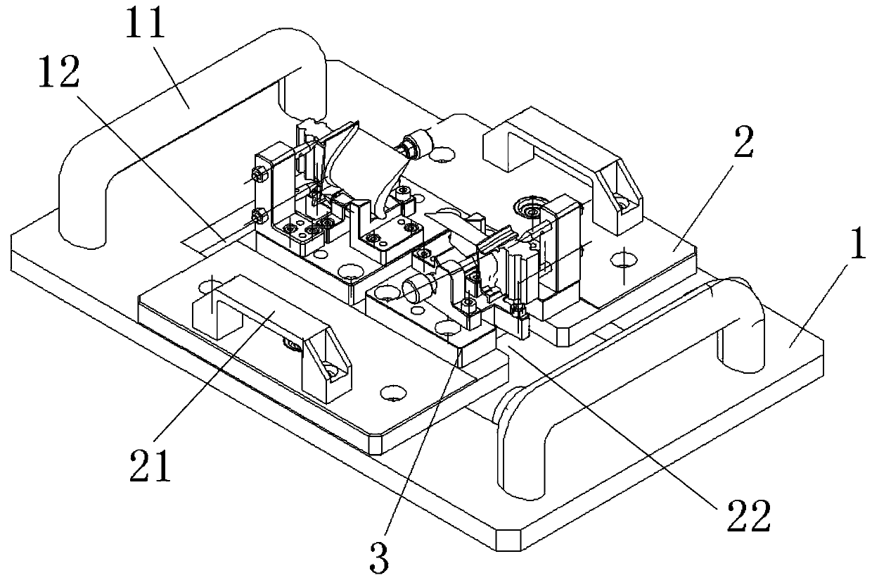
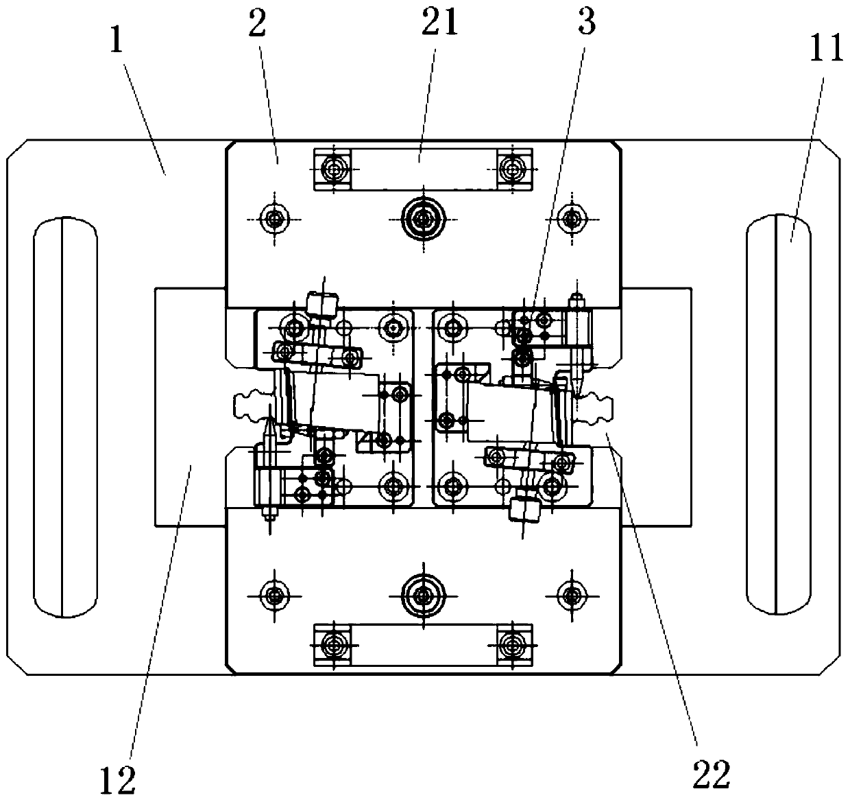
[0023] A method for detecting the mortise tooth profile of a turbine working blade, which uses a transmission device to load and unload materials on a detection workbench, and detects through a detection device and a computer. It is characterized in that it includes the following steps:

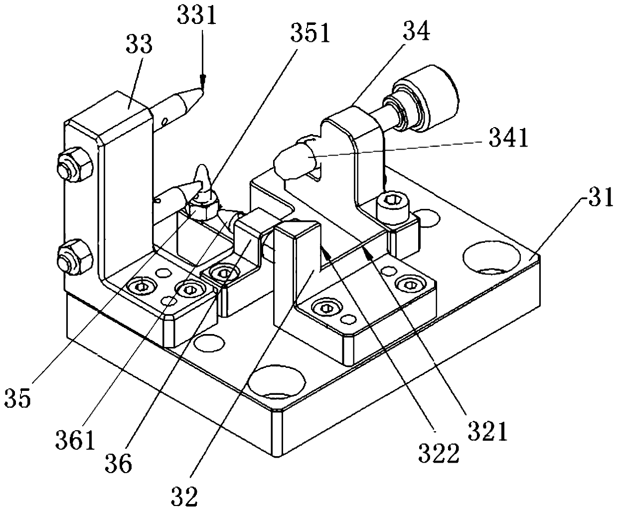
[0024] a. Compile a special testing program according to the computer class in the profile requirements of the tenon teeth of the blade; and design and manufacture a special positioning device for clamping the blade for testing. The design and manufacturing steps of the special positioning device are:

[0025] Analyze the size and basic shape, positioning requirements, and detection requirements of the tenon tooth profile of the turbine working blade, and propose a device desi...


PUM


Abstract

The invention relates to the field of an aero-engine blade and particularly relates to a turbine working blade tenon tooth profile detection method. A conveying device is used for feeding and discharging materials to a detection workbench, and detection is conducted through detection equipment and a computer. The method comprises steps that a special detection program is compiled according to thecomputer class in the blade tenon tooth profile requirement, and a special positioning device used for clamping a blade is designed and manufactured according to the drawing size; feeding at a feedingposition on a side surface of the detection workbench is carried out; positioning is carried out by the special positioning device; the computer executes the special detection program and controls detection equipment to detect the blade clamped on the special positioning device, detection data is sent to the computer in real time, and the computer automatically stores the data and outputs a report. The method is advantaged in that the blade is clamped into the special positioning device designed according to the drawing size, automatic measurement of the blade tenon tooth profile is achievedthrough the compiled special detection program, automatic data and report storage is achieved, and a problem that to-be-detected blades need to be detected during traditional inspection and acceptancein the working procedure is solved.

Description

technical field [0001] The invention relates to the field of aero-engines, in particular to a method for detecting the tenon tooth profile of a turbine working blade and a special positioning device. Background technique [0002] At present, the working blade of the aero-engine turbine is an important part of the turbine component and also an important key part of the entire engine. It has a large number of parts and requires high machining dimensional accuracy. In the traditional process, the tenon tooth profile of this type of part is manually detected. The profile of the tenon tooth is projected on the special projector inspection equipment through the positioning of the measuring tool, and the enlarged image is compared with the profile of the tenon tooth processed by the blade. The following problems exist in the measurement method: manual measurement can only judge whether it is qualified or not, and cannot be saved Relevant data; the repetition accuracy of manual meas...

Claims


Application Information

Patent Timeline
Patent Type & Authority Applications(China)
IPC IPC(8): G01B11/24
CPCG01B11/2433
Inventor 田灿韩丹李扬
Owner GUIYANG AVIC POWER PRECISION CASTING
Why Eureka
Try Eureka