Eureka AIR delivers breakthrough ideas for toughest innovation challenges, trusted by R&D personnel around the world.

Antenna scanning direction control method and device and antenna system

A scanning direction and direction control technology, which is applied to antennas, transmission systems, transmission monitoring, etc., can solve the problems of adjustment, ignoring the judgment of environmental sensitivity, and occupying a large amount of processor computing time, so as to improve selection efficiency, simple algorithm, The effect of improving accuracy

Inactive Publication Date: 2020-04-17
普联国际有限公司
View PDF11 Cites 0 Cited by
  • Summary
  • Abstract
  • Description
  • Claims
  • Application Information

AI Technical Summary

Problems solved by technology

However, in the case of a large number of array antenna subunits, the number of mode combinations increases exponentially with the number of antenna subunits, and the number of traversal combinations is large, resulting in too much processor computing time, which is not suitable for actual products
In addition, although RSSI is easy to obtain and easy to compare, there is no divide-and-conquer strategy for the received RSSI value to adjust the corresponding antenna combination, ignoring the judgment of the sensitivity to the environment, and collecting the RSSI corresponding to different antenna combinations When the time span may be long, it is not applicable when the working environment of the product changes rapidly, and the accuracy of directional adjustment of the antenna direction is not high

Method used


Image

  • Antenna scanning direction control method and device and antenna system
  • Antenna scanning direction control method and device and antenna system
  • Antenna scanning direction control method and device and antenna system

Examples


Embodiment Construction

[0036] The following will clearly and completely describe the technical solutions in the embodiments of the present invention with reference to the accompanying drawings in the embodiments of the present invention. Obviously, the described embodiments are only some, not all, embodiments of the present invention. Based on the embodiments of the present invention, all other embodiments obtained by persons of ordinary skill in the art without creative efforts fall within the protection scope of the present invention.

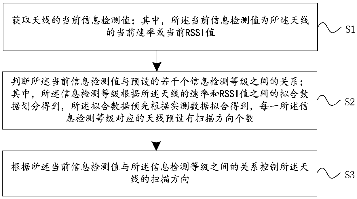
[0037] see figure 1 , figure 1 It is a flowchart of a method for controlling an antenna scanning direction provided by an embodiment of the present invention; the method for controlling an antenna scanning direction includes:

[0038] S1. Obtain the current information detection value of the antenna; wherein the current information detection value is the current rate or the current RSSI value of the antenna;

[0039] S2. Judging the relationship between the curre...


PUM


Abstract

The invention discloses an antenna scanning direction control method. The method comprises the following steps: acquiring a current information detection value of an antenna, wherein the current information detection value is a current rate or a current RSSI value of the antenna; judging the relation between the current information detection value and a plurality of preset information detection levels, wherein the information detection levels are obtained by dividing fitting data between the rates of the antennas and RSSI values, the fitting data are obtained by fitting according to actual measurement data in advance, and the number of scanning directions of the antenna corresponding to each information detection level is preset; and controlling the scanning direction of the antenna according to the relationship between the current information detection value and the information detection level. The invention also discloses an antenna scanning direction control device and an antenna system. By adopting the embodiment of the invention, the algorithm is simple, the selection efficiency of the antenna scanning direction is improved, and the accuracy of directionally adjusting the antenna scanning direction is also improved.

Description

technical field [0001] The present invention relates to the technical field of antennas, in particular to a method, device and antenna system for controlling the scanning direction of an antenna. Background technique [0002] At present, most wireless terminal devices, such as routers and smart home products, use omnidirectional antennas to obtain coverage in all directions. But usually there are not users in all directions at a specific moment, and there will be a waste of energy in these directions. If the antenna radiation direction can be directed to users, it can improve the user's received signal strength, improve communication quality, and increase coverage distance. , and the location of the user is often changing dynamically, which requires a type of antenna whose direction can be adjusted dynamically. [0003] The antenna whose direction can be adjusted dynamically in the prior art usually takes the received RSSI (Received Signal Strength Indication) as the judgme...

Claims


Application Information

Patent Timeline
IPC IPC(8): H04B17/318H04B17/309H04B17/20H01Q3/00
CPCH01Q3/00H04B17/20H04B17/309H04B17/318
Inventor 邓文龙
Owner 普联国际有限公司
Why Eureka
Eureka Blog
Learn More