MEMS MIC with front sound cavity and rear sound cavity

A technology of rear sound cavity and ASIC chip, which is applied in the field of front rear sound cavity MEMSMIC, can solve the problems of the size limit of MEMSMIC rear sound cavity, limit the sound pickup performance of MEMS chip, and it is difficult to further improve the sensitivity, and achieve the largest volume of the rear sound cavity The sound of the product is clear, and the effect of improving the volume of the rear sound cavity is too small

Pending Publication Date: 2020-04-17
山东新港电子科技有限公司
View PDF0 Cites 2 Cited by
  • Summary
  • Abstract
  • Description
  • Claims
  • Application Information

AI Technical Summary

Problems solved by technology

In this way, the volume of the rear sound cavity depends on the volume of the back cavity of the MEMS chip, and the adjustable range is limited. The size of the MEMS MIC rear sound cavity is very limited. The small volume of the rear sound cavity limits the sound pickup performance of the MEMS chip, making it difficult to further improve the sensitivity of the MEMS MIC with the current structure.

Method used


Image

  • MEMS MIC with front sound cavity and rear sound cavity
  • MEMS MIC with front sound cavity and rear sound cavity
  • MEMS MIC with front sound cavity and rear sound cavity

Examples


Embodiment 1

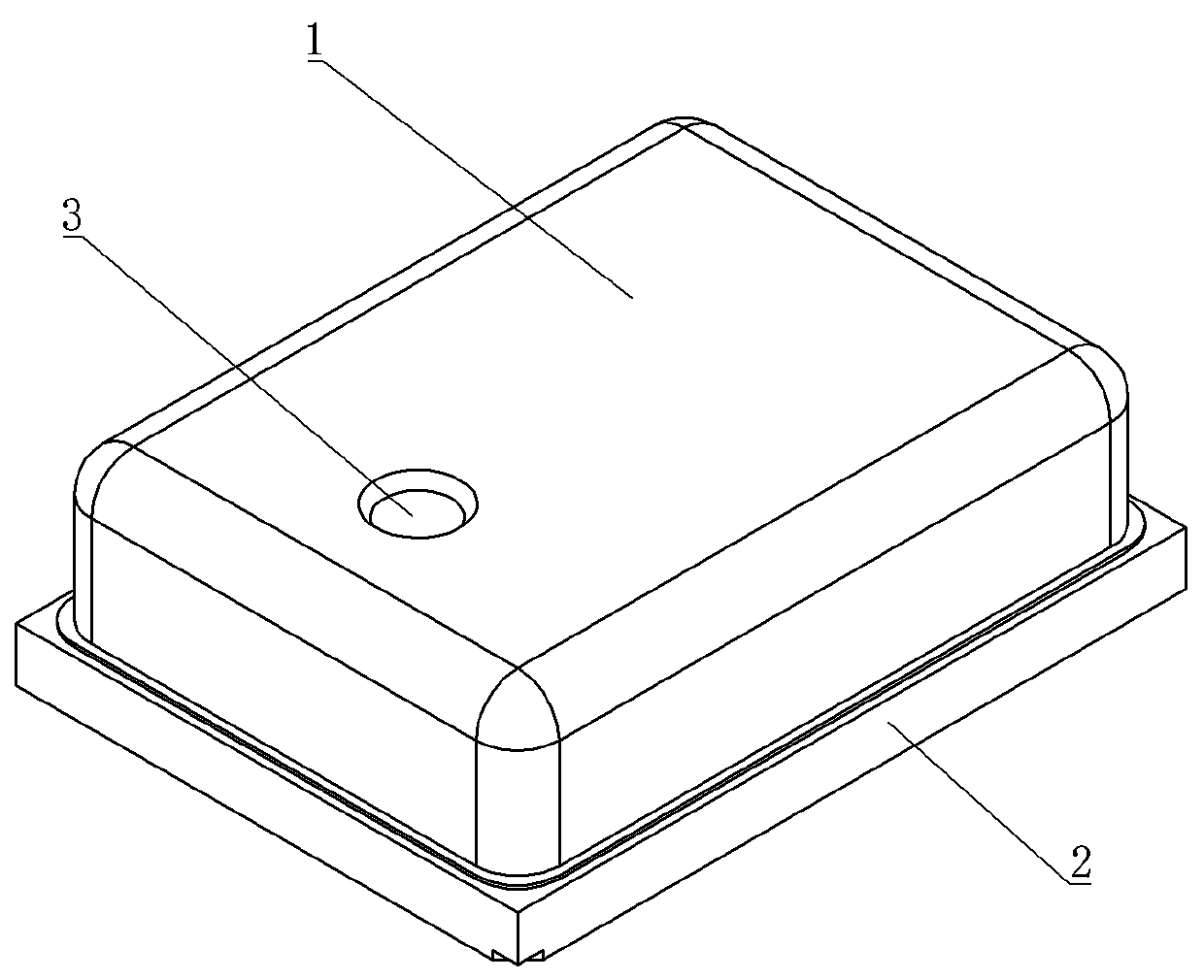
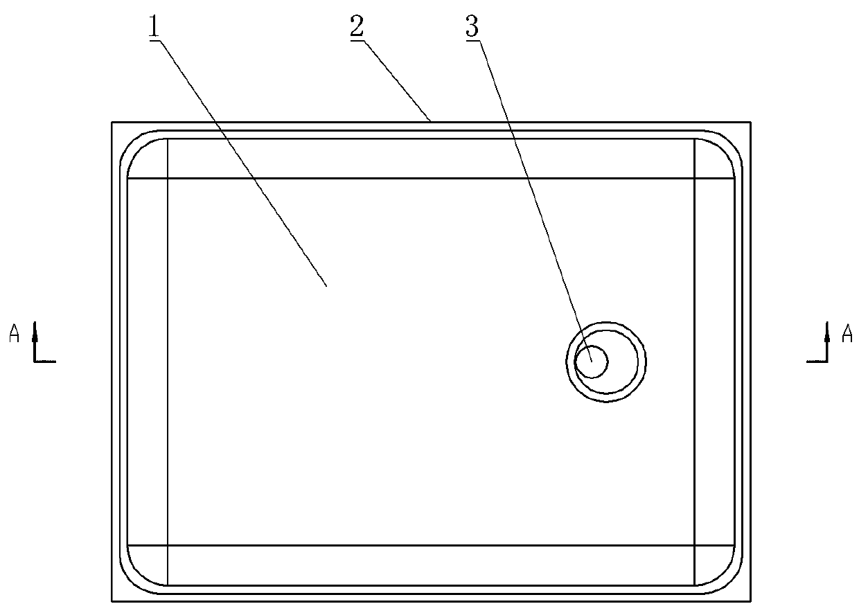
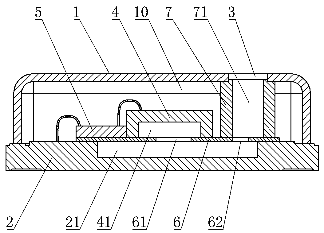
[0025] Embodiment 1: as attached Figures 1 to 6 As shown, the pre-rear sound cavity MEMS MIC includes a sound cavity shell 1, and the sound cavity shell 1 is provided with a sound inlet 3, and the sound cavity shell 1 is connected to a PCB2, and the sound cavity shell 1 1 is provided with a MEMS sound pressure sensor chip 4 and an ASIC chip 5, the MEMS sound pressure sensor chip 4 is provided with a rear sound chamber 41, the sound chamber housing 1 is provided with a cavity plate 6, and the MEMS sound pressure sensor chip The pressure sensor chip 4 is installed on the cavity plate 6, and the sound transmission cavity 21 is formed between the cavity plate 6 and the PCB2, and the cavity plate 6 is provided with a first sound transmission hole 61 communicating with the sound transmission cavity 21 and The second sound transmission hole 62, the rear sound cavity 41 communicates with the sound transmission cavity 21 through the first sound transmission hole 61, and the communicat...

Embodiment 2

[0032] Embodiment 2: as attached Figure 7 As shown, in this embodiment, there is a MEMS MIC in front of the rear sound cavity, and the sound transmission cavity 21 is jointly formed by the hollow part on the PCB 2 and the concave cavity on the cavity plate 6 . This makes the sound transmission cavity 21 larger, the sound transmission effect is better, the sound pickup effect is better, the sensitivity is higher, the product voice is clear, natural, easy to identify, and the product sound quality is significantly improved.

[0033] The remaining parts are the same as in Embodiment 1 in this embodiment.


PUM


Abstract

The invention discloses an MEMS MIC with a front sound cavity and a rear sound cavity. The appearance structure is kept unchanged. An expanded rear sound cavity communicated with the rear sound cavityis formed by adding a cavity plate on a PCB. The MEMS MIC internal structure is changed. The industry common problem that the rear sound cavity of the advancing MEMS MIC is small is fundamentally solved. The utilization rate of the internal space of the MIC is maximized. The rear sound cavity volume is maximized. The problem that the volume of a traditional rear sound cavity completely depends onthe size of an MEMS sound pressure sensor chip is thoroughly solved. The current situation that the rear sound cavity volume is too small and the front and rear sound cavity volumes are not matched can be effectively improved. The size of the rear sound cavity is increased, so that the amplitude of the MEMS chip is increased. The pickup sensitivity is remarkably improved. The product sensitivityis remarkably improved under the condition that the appearance structure and the overall size are kept unchanged. The product voice is clear, natural and easy to identify, and the product tone qualityis remarkably improved.

Description

technical field [0001] The invention relates to the field of MEMS MICs, in particular to a MEMS MIC with front and rear sound chambers. Background technique [0002] MEMS MIC is a microphone based on MEMS technology, consisting of MEMS sound pressure sensor chip, ASIC chip, front and rear sound chambers and RF suppression circuit. The MEMS sound pressure sensor is a miniature capacitor composed of a silicon diaphragm and a silicon back plate, which can convert the change of sound pressure into a change of capacitance, and then the ASIC chip converts the change of capacitance into an electrical signal to realize "sound-to-electricity" conversion . Among them, the MEMS chip divides the cavity formed by the MEMS shell into a front sound cavity and a rear sound cavity. The rear sound cavity of the forward-sounding MEMS MIC is mainly formed by bonding the MEMS chip and the PCB through glue. In this way, the volume of the rear sound cavity depends on the volume of the back cavit...

Claims


Application Information

Patent Timeline
Patent Type & Authority Applications(China)
IPC IPC(8): H04R19/04
CPCH04R19/04H04R2201/003
Inventor 刘志永朱法超
Owner 山东新港电子科技有限公司
Why Eureka
Try Eureka