Large layout and processing method of optical module PCB product
A processing method and technology of optical modules, which are applied in the simultaneous processing of multiple printed circuits, the structural connection of printed circuits, printed circuit components, etc., can solve problems such as low production efficiency, small size of PCB boards, and high labor intensity. , to achieve the effect of improving the efficiency of production and processing, reducing the time of repeated work, and improving production efficiency
Inactive Publication Date: 2020-04-17
BRAIN POWER (QING YUAN) CO LTD
View PDF4 Cites 3 Cited by
- Summary
- Abstract
- Description
- Claims
- Application Information
AI Technical Summary
Benefits of technology
The technical effect of this new design for an opto-electronic device (OE) package includes improved manufacturing efficiencies due to two or multiple OEE packages being joined together at specific locations on their circuit board(s). This allows for automatic cleanings after each step while still maintaining high levels of quality control over final products produced. Additionally, there're also benefits from fast assembly times that reduce repetitive tasks and increase overall production speed compared to previous designs.
Problems solved by technology
This technical problem addressed by these inventors relates to improving the manufacturing process of opto modules (optics) due to their smaller sizes compared with traditional packages that use larger components like transistors or other devices). Additionally, there may exist issues related to maintain stability when handling multiple layers on top of each others without damaging any device inside it. These challenges can make the overall design time-consuming and expensive.
Method used
View moreImage
Smart ImageViewing Examples

Examples
 PUM
| Property | Measurement | Unit |
|---|---|---|
| Aperture | aaaaa | aaaaa |
| Width | aaaaa | aaaaa |
| Width | aaaaa | aaaaa |
Abstract
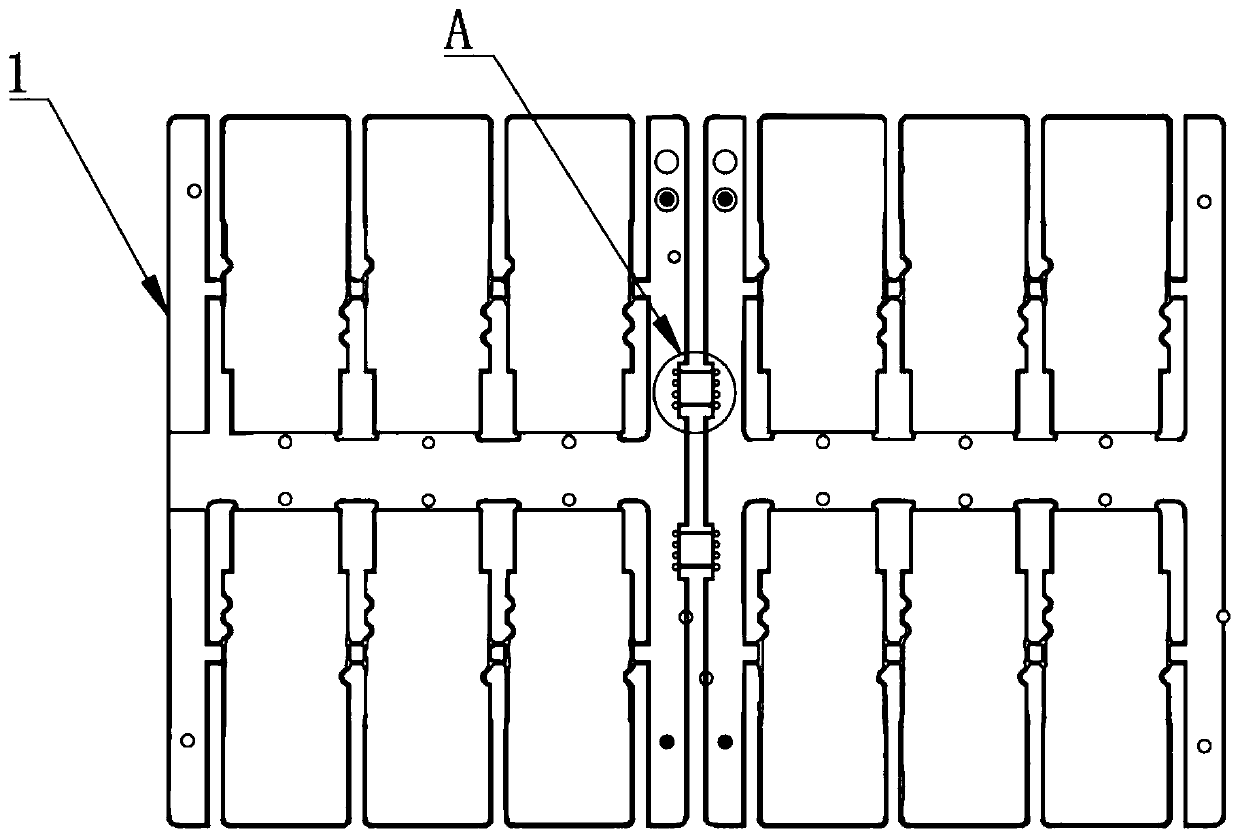
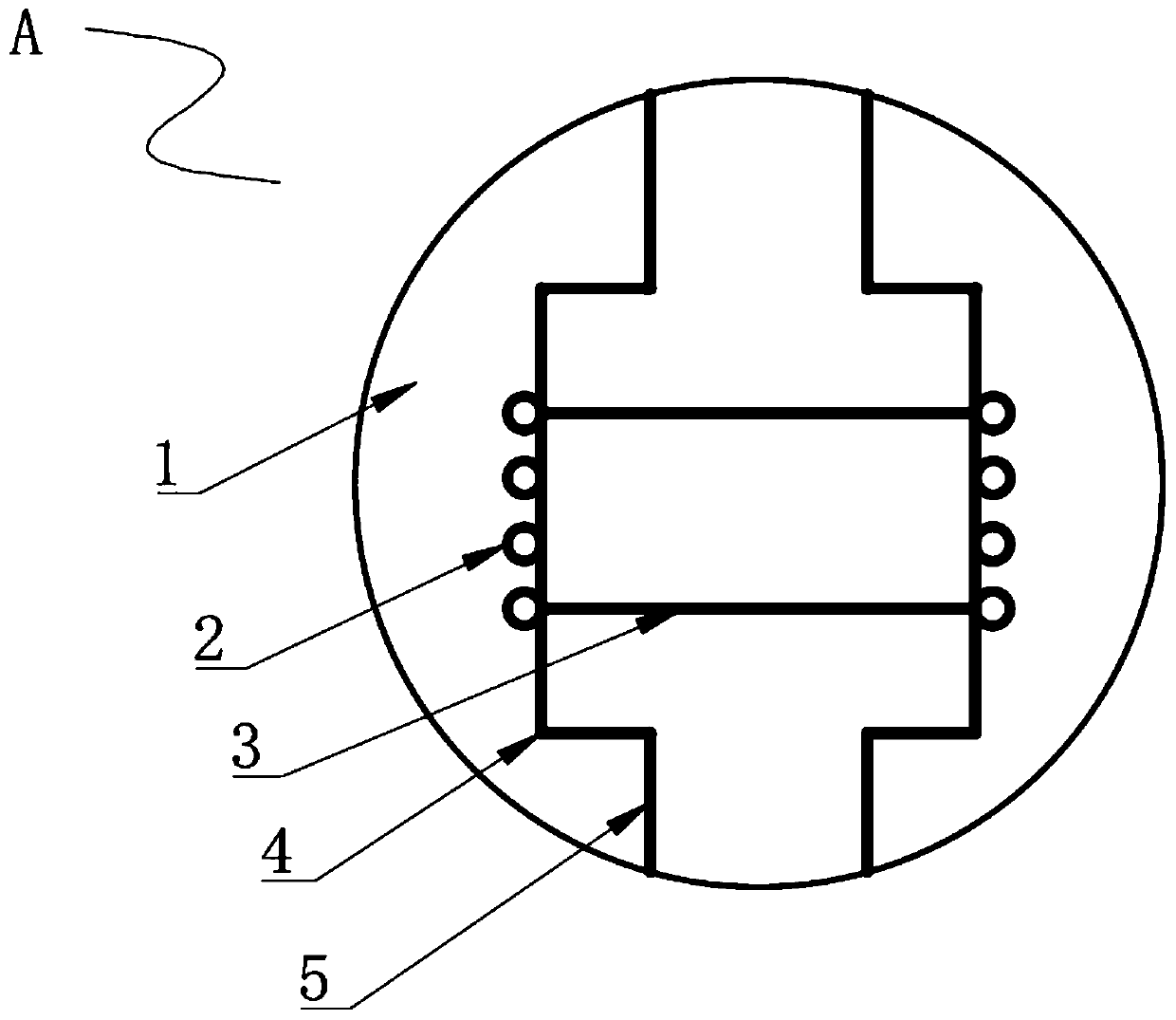
The invention relates to the technical field of circuit board processing, and discloses a large layout and processing method of an optical module PCB product. The product comprises at least two PCBs.A connecting bridge is connected between every two adjacent PCBs; a groove edge is arranged in the middle of one end of the PCB and located on one side of the connecting bridge, broken edges are arranged at the positions, close to the upper end and the lower end of the connecting bridge, of one end of the PCB, a plurality of stamp holes are formed in the positions, located on one side of the groove edge, of the front side of the PCB, and the two ends of the connecting bridge are connected with the corresponding groove edges respectively. Two or more optical module PCBs are connected together through the connecting bridges and the stamp holes so that the manufacturing and processing efficiency of subsequent station processes can be improved; and in the finished product cleaning process, thefinished products can automatically pass through the horizontal cleaning production line, the optical module PCBs do not need to be pasted together through adhesive tape, the repeated working time isshortened, the finished products can be manually broken off and then delivered after being cleaned without increasing extra repeated machining, and convenience and rapidness are achieved.
Description
Login to View More Claims
Login to View More Application Information
Patent Timeline
 Owner BRAIN POWER (QING YUAN) CO LTD
Features
- R&D
- Intellectual Property
- Life Sciences
- Materials
- Tech Scout
- Unparalleled Data Quality
- Higher Quality Content
- 60% Fewer Hallucinations
Learn More Browse by: Latest US Patents, China's latest patents, Technical Efficacy Thesaurus, Application Domain, Technology Topic, Popular Technical Reports.
© 2025 PatSnap. All rights reserved.Legal|Privacy policy|Modern Slavery Act Transparency Statement|Sitemap|About US| Contact US: help@patsnap.com