Metal contaminated soil remediation device

A technology of polluted soil and soil, which is applied in the field of contaminated soil remediation and management, can solve the problems of insufficient soil remediation and inability to ensure full contact of soil, and achieve the effect of ensuring the effect of remediation

Inactive Publication Date: 2020-04-21
于瑞祚
View PDF1 Cites 23 Cited by
  • Summary
  • Abstract
  • Description
  • Claims
  • Application Information

AI Technical Summary

Problems solved by technology

However, this device cannot ensure that the large pieces of soil in the crushing process are in sufficient contact with the spraying agent, so that the soil remediation is insufficient

Method used


Image

  • Metal contaminated soil remediation device
  • Metal contaminated soil remediation device
  • Metal contaminated soil remediation device

Examples


specific Embodiment approach 1

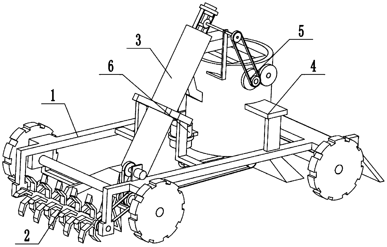
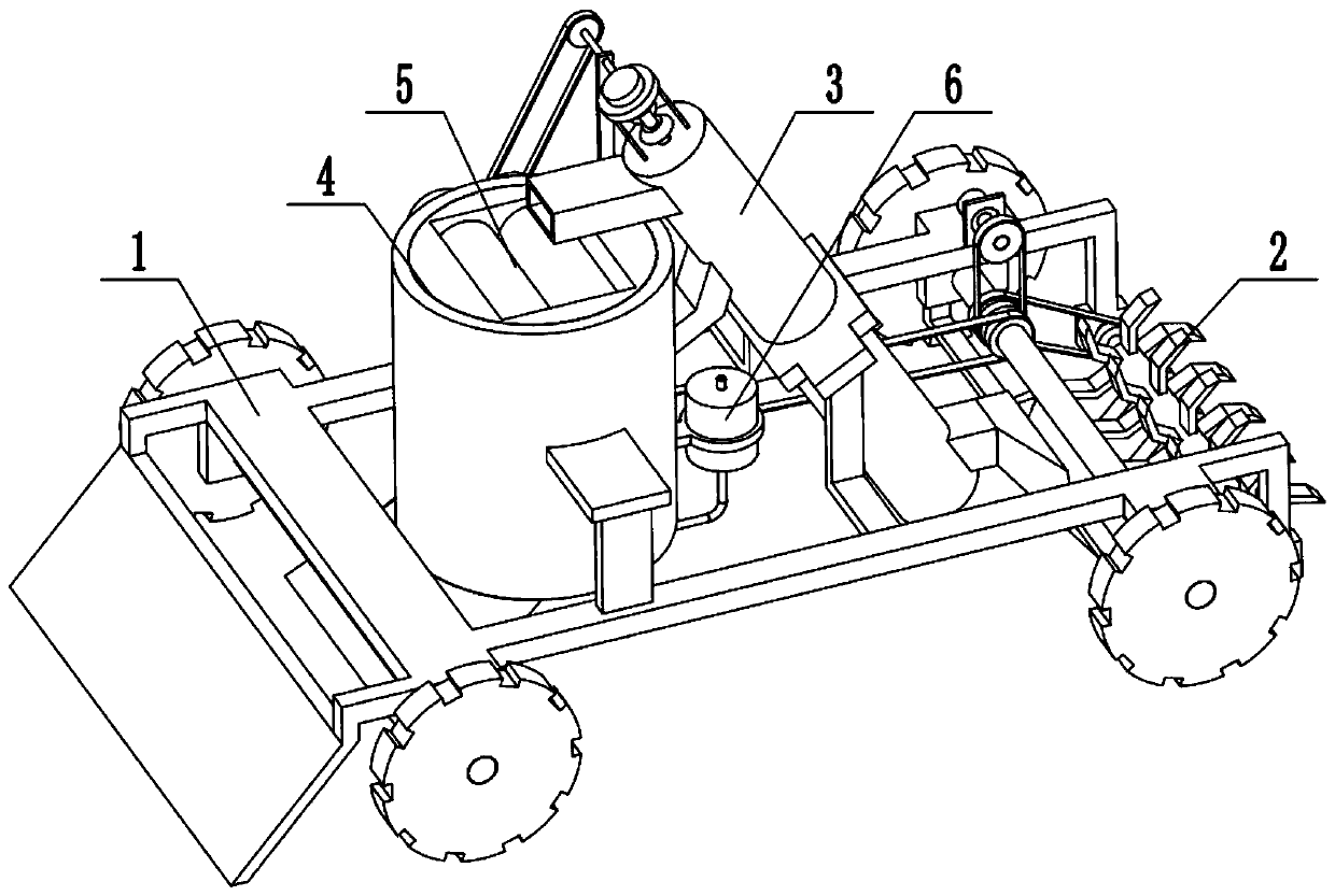
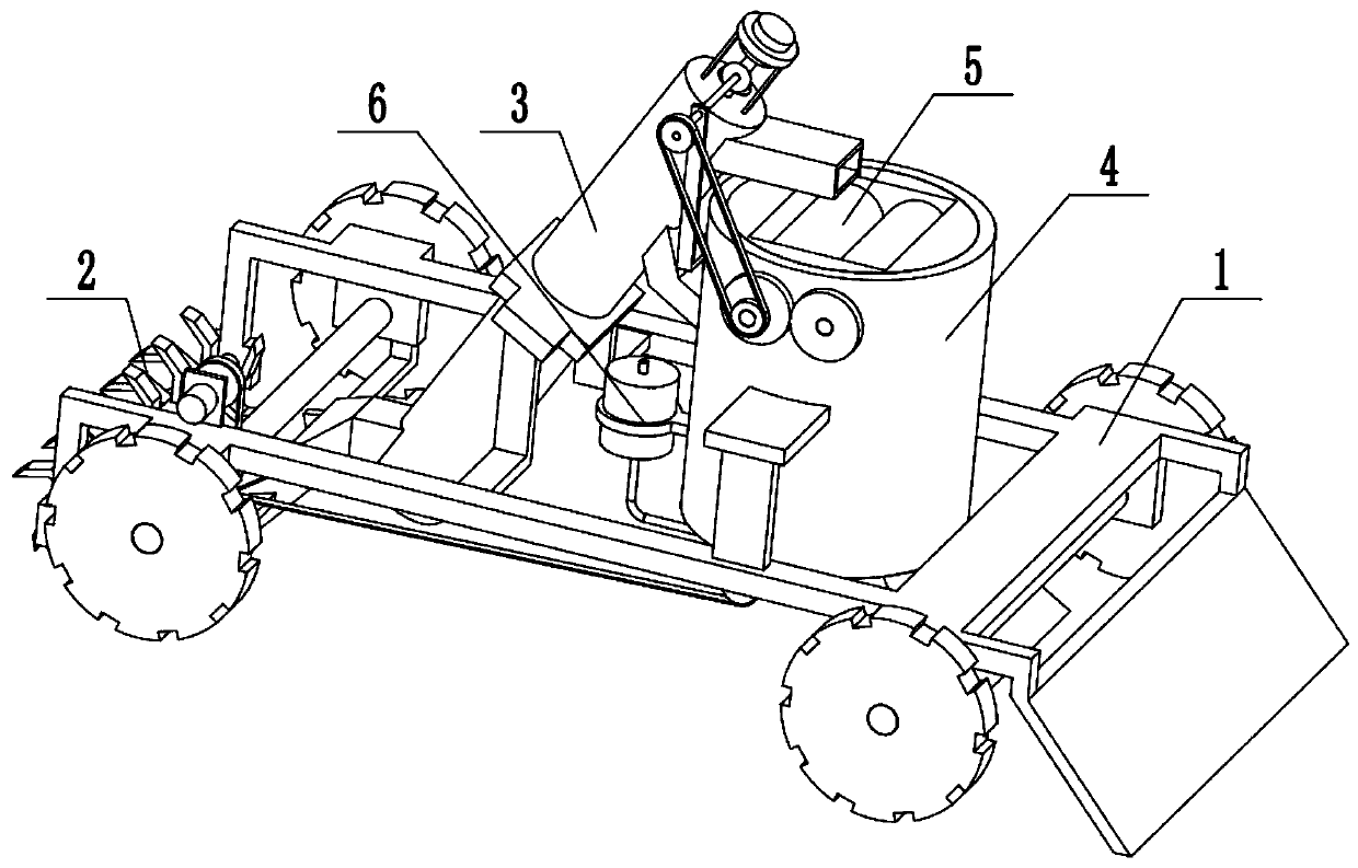
[0034] Combine below Figure 1-14 Describe this embodiment, a metal-contaminated soil remediation device, including a movable chassis 1, a soil plowing part 2, a soil collection and transportation mechanism 3, a soil spray cylinder assembly 4, a soil block crushing mechanism 5, and a soil spray mechanism 6, The soil plowing part 2 is arranged on one end of the movable underframe 1, the soil plowing part 2 is connected with the movable underframe 1 in transmission, the soil collecting and conveying mechanism 3 is arranged on the movable underframe 1, and one end of the soil collecting and conveying mechanism 3 Located on one side of the soil plowing part 2, the other end of the soil collection and conveying mechanism 3 is located above the soil spray cylinder assembly 4, the soil spray cylinder assembly 4 is located at the other end of the movable chassis 1, and the soil block crushing mechanism 5 is provided Above the soil spraying cylinder assembly 4, the soil block crushing ...

specific Embodiment approach 2

[0036] Combine below Figure 1-14 To illustrate this embodiment, the movable underframe 1 includes a wheel frame 1-1, a first wheel shaft 1-2, a second wheel shaft 1-3, a roller 1-4, a travel drive motor 1-5, a first pulley 1- 6. The second pulley 1-7, the third pulley 1-8, the fourth pulley 1-9, the support frame 1-10 and the scraping plate 1-11; the first axle 1-2 and the second axle 1-3 rotate respectively Connected to the left and right ends of the wheel frame 1-1, the two ends of the first wheel shaft 1-2 and the second wheel shaft 1-3 are respectively fixedly connected to a roller 1-4, and the walking drive motor 1-5 is fixedly connected to the wheel by the motor frame. On the left side of the frame 1-1, the output shaft of the travel drive motor 1-5 is fixedly connected to the first pulley 1-6, and the first pulley 1-6 is connected to the second pulley 1-7 through a belt transmission, and the second pulley 1- 7. The third pulley 1-8 and the fourth pulley 1-9 are all fi...

specific Embodiment approach 3

[0038] Combine below Figure 1-14 Illustrate this embodiment, described soil loosening part 2 comprises turning plate rotating shaft 2-1, turning loose plate 2-2, the 5th belt pulley 2-3 and axle frame plate 2-4; Connect a plurality of loosening plates 2-2, the fifth belt pulley 2-3 is fixedly connected on the turning shaft 2-1, and the two ends of the turning shaft 2-1 are respectively rotated to connect a shaft frame plate 2-4, two shafts The frame plates 2-4 are all fixedly connected to the left side of the wheel frame 1-1, and the fourth pulley 1-9 is connected with the fifth pulley 2-3 through belt transmission. The fourth pulley 1-9 drives the fifth pulley 2-3 to rotate counterclockwise, the fifth pulley 2-3 drives the turning shaft 2-1 to rotate counterclockwise, and the turning shaft 2-1 drives a plurality of loosening plates 2 on it -2 rotates counterclockwise, and a plurality of loosening plates 2-2 rotate around the axis of the turning shaft 2-1 to suddenly loosen....


PUM


Abstract

The invention relates to the technical field of contaminated soil remediation treatment, in particular to a metal contaminated soil remediation device which comprises a movable bottom frame, a soil scarifying part, a soil collecting and conveying mechanism, a soil spraying barrel assembly, a soil block crushing mechanism and a soil spraying mechanism. The metal contaminated soil remediation devicehas the beneficial technical effects that soil blocks and crushed soil can be screened, the crushed soil makes direct contact with a spraying agent and then is discharged, large soil blocks are ground into crushed soil and then make contact with the spraying agent and then are discharged, a spray head conducts rotary spraying, full contact with soil can be performed, and the remediation effect isguaranteed. The soil scarifying part is arranged at one end of the movable bottom frame and is in transmission connection with the movable bottom frame, the soil collecting and conveying mechanism isarranged on the movable bottom frame, one end of the soil collecting and conveying mechanism is located on one side of the soil scarifying part, and the other end of the soil collecting and conveyingmechanism is located above the soil spraying barrel assembly. The soil spraying cylinder assembly is arranged at the other end of the movable bottom frame, and the soil block crushing mechanism is arranged above the soil spraying cylinder assembly.

Description

technical field [0001] The invention relates to the technical field of remediation and treatment of contaminated soil, in particular to a metal-contaminated soil remediation device. Background technique [0002] The patent number is CN201821357992.3 for a mobile soil pollution in-situ remediation device. The utility model discloses a mobile soil pollution in-situ remediation device, which includes a main body box, and a stirring box is fixedly connected to the left side of the top of the main body box , the bottom of the inner wall of the main body box is fixedly connected with a sound-absorbing cover, and the bottom of the inner wall of the sound-absorbing cover is fixedly connected with a first motor, and the output shaft of the first motor is fixedly connected with a movable rod, and the movable rod is far away from one end of the first motor It runs through the sound-absorbing cover and extends to the outside of the sound-absorbing cover, and the surface of the active ro...

Claims


Application Information

Patent Timeline
Patent Type & Authority Applications(China)
IPC IPC(8): A01B49/02A01B49/04A01B77/00B09C1/08B02C4/02B02C21/02B07B1/28
CPCA01B49/022A01B49/04A01B77/00B02C4/02B02C21/02B07B1/005B07B1/28B09C1/08B09C2101/00
Inventor 于瑞祚
Owner 于瑞祚
Why Eureka
Try Eureka