
A kind of steel structure automatic forming equipment

An automatic forming, steel structure technology, applied in shearing machine equipment, metal processing equipment, manufacturing tools, etc., can solve problems such as loss of machine service life, air-conditioning leakage, time-consuming and laborious, etc., to prolong service life and facilitate positioning and cutting. , Guarantee the effect of product quality

Active Publication Date: 2021-04-16
XUZHOU NANFANG YONGCI MATERIAL
View PDF5 Cites 0 Cited by
  • Summary
  • Abstract
  • Description
  • Claims
  • Application Information

AI Technical Summary

Problems solved by technology

[0003] However, there are still many disadvantages in the existing steel forming equipment. When in use, the steel cannot be positioned and cut on the support block, which affects the product quality of the steel. In addition, the internal temperature of the equipment is too high. When the first connecting plate is transmitting cold air to cool down, the shell If the connection between the body and the cold air pipe is not tight, the cold air will leak, which will reduce the cooling efficiency of the equipment and damage the service life of the machine. Also, when the equipment needs to replace the blade on the blade board, the process of disassembling the blade board is cumbersome and time-consuming. problem, for which we propose a steel structure automatic forming equipment

Method used


Image

  • A kind of steel structure automatic forming equipment
  • A kind of steel structure automatic forming equipment
  • A kind of steel structure automatic forming equipment

Examples


Embodiment Construction

[0025] The following will clearly and completely describe the technical solutions in the embodiments of the present invention with reference to the accompanying drawings in the embodiments of the present invention. Obviously, the described embodiments are only some, not all, embodiments of the present invention. Based on the embodiments of the present invention, all other embodiments obtained by persons of ordinary skill in the art without making creative efforts belong to the protection scope of the present invention.

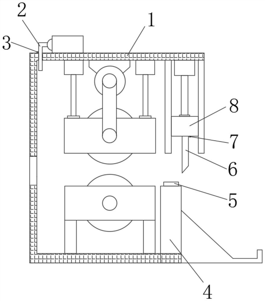
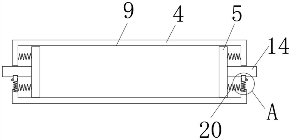
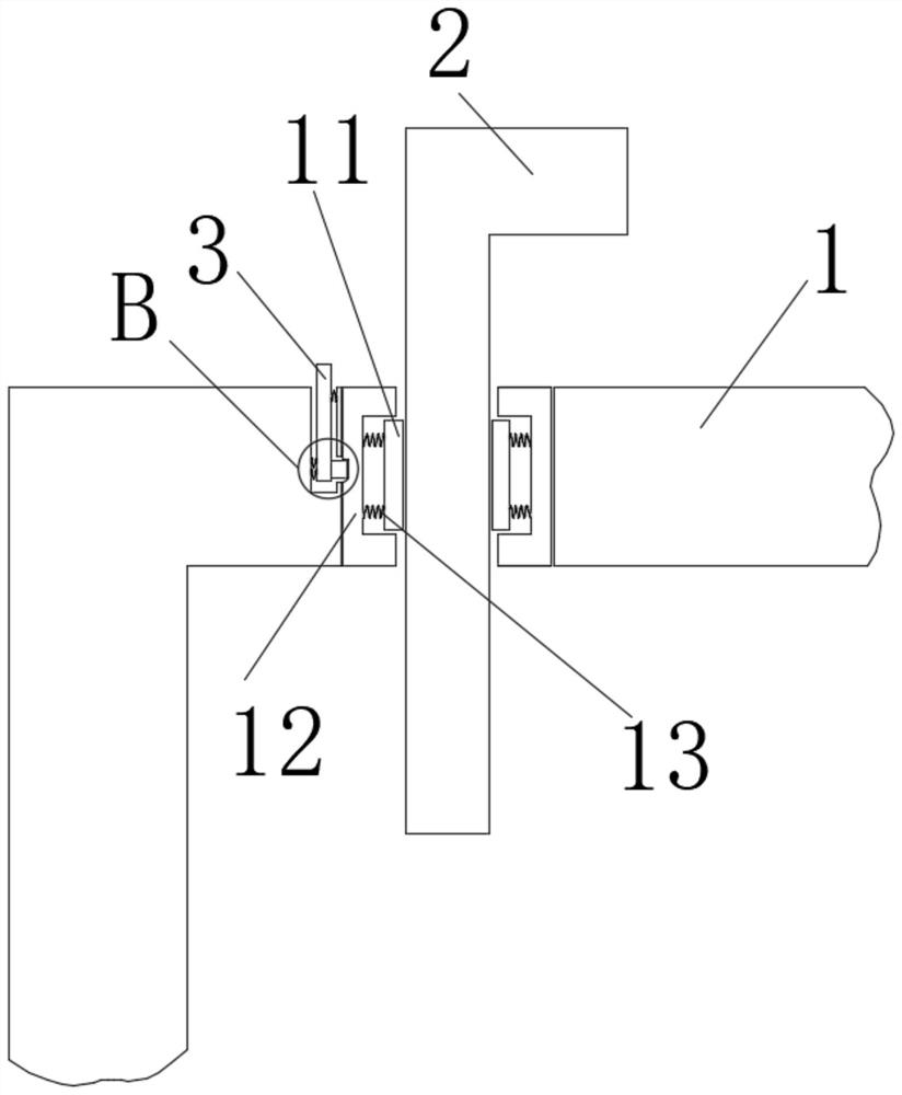
[0026] see Figure 1-7 , the present invention provides a technical solution: a steel structure automatic forming equipment, including a housing 1, a support block 4, a positioning mechanism, a sealing mechanism and a disassembly mechanism, the positioning mechanism is located on the top surface of the support block 4, and the positioning mechanism includes a fixed plate 5, The top surface of the support block 4 is provided with a placement groove 9, and one s...


PUM


Abstract

The invention discloses a steel structure automatic forming equipment, which comprises a casing, a support block, a positioning mechanism, a sealing mechanism and a disassembly mechanism, the positioning mechanism is located on the top surface of the support block, the positioning mechanism includes a fixing plate, the support The top surface of the block is provided with a placement groove, and one side of the fixing plate is located inside the placement groove; the present invention effectively prevents the steel from being unable to be fixed on the support block by setting the fixing plate, which is convenient for positioning and cutting, thereby ensuring that the steel Excellent product quality, through the set sealing ring, it can effectively prevent the internal temperature of the equipment from being too high. When the first connecting plate transmits cold air to cool down, the connection between the shell and the cold air pipe is not tight, which will cause the cold air to leak out, ensuring the cooling of the equipment. Efficiency prolongs the service life of the machine. Through the set button, it effectively avoids the cumbersome process of disassembling the blade when the equipment needs to replace the blade on the blade board, saving labor costs.

Description

technical field [0001] The invention belongs to the technical field of steel forming equipment, and in particular relates to an automatic forming equipment for steel structures. Background technique [0002] my country's crude steel output ranks first in the world. The annual output of crude steel of the top ten domestic iron and steel enterprises is more than 10 million tons. In recent years, iron and steel restructuring has entered the fast lane, such as Guangdong Iron and Steel Group controlled by Baosteel, Shandong Iron and Steel Group mainly formed by Shandong Jigang and Laiwu Steel, and Hebei Iron and Steel Group. [0003] However, there are still many disadvantages in the existing steel forming equipment. When in use, the steel cannot be positioned and cut on the support block, which affects the product quality of the steel. In addition, the internal temperature of the equipment is too high. When the first connecting plate is transmitting cold air to cool down, the s...

Claims


Application Information

Patent Timeline
Patent Type & Authority Patents(China)
IPC IPC(8): B23D15/04B23D33/00B23D35/00B23Q11/10
CPCB23D15/04B23D33/00B23D35/002B23Q11/10
Inventor 张作州
Owner XUZHOU NANFANG YONGCI MATERIAL
Learn More