Positioning system for flange welding and welding method

A positioning system and flange welding technology, applied in welding equipment, welding equipment, welding accessories, etc., can solve problems such as positioning failures

Active Publication Date: 2020-04-21
唐山文丰重工有限公司
View PDF13 Cites 1 Cited by
  • Summary
  • Abstract
  • Description
  • Claims
  • Application Information

AI Technical Summary

Problems solved by technology

However, the shrinkage and axial alignment of the flange will affect each other, for example, if the flange is first pressed to align axially, then the weld cannot be pushed and shrunk
As another example, when first shrinking the weld seam and then pushing the weld seam up and down to implement axial alignment, the opposite side walls of the weld seam tend to interfere with each other when moving up and down, thereby causing positioning failure

Method used


Image

  • Positioning system for flange welding and welding method
  • Positioning system for flange welding and welding method
  • Positioning system for flange welding and welding method

Examples


Embodiment Construction

[0024] In order to facilitate the understanding of the present invention, the present invention will be described more fully below with reference to the associated drawings. Preferred embodiments of the invention are shown in the accompanying drawings. However, the present invention can be embodied in many different forms and is not limited to the embodiments described herein. On the contrary, the purpose of providing these embodiments is to make the disclosure of the present invention more thorough and comprehensive.

[0025] It should be noted that when an element is referred to as being “fixed” to another element, it can be directly on the other element or there can also be an intervening element. When an element is referred to as being "connected to" another element, it can be directly connected to the other element or intervening elements may also be present. The terms "vertical," "horizontal," "left," "right," and similar expressions are used herein for purposes of ill...


PUM


Abstract

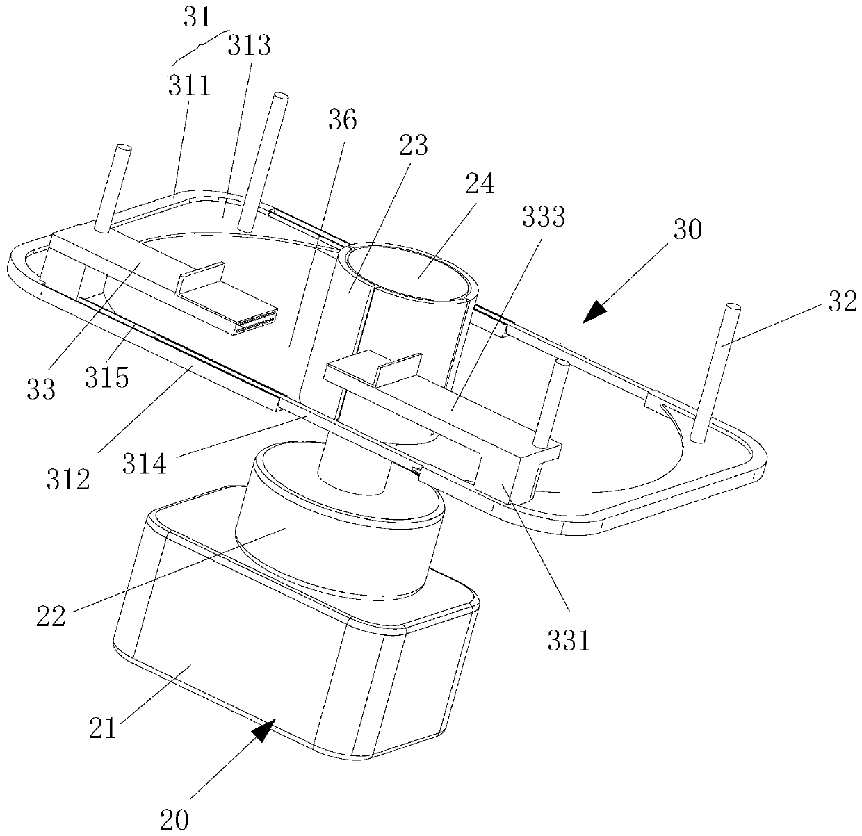
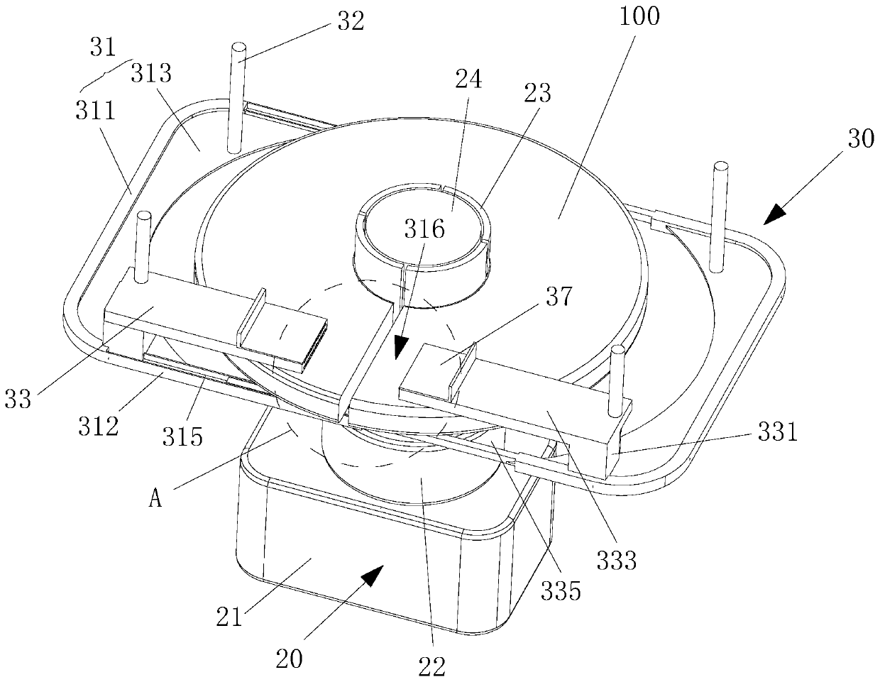
The invention relates to a positioning system for flange welding and a welding method. The positioning system for flange welding comprises a clamping jaw assembly and two transverse pushing assemblies, wherein the clamping jaw assembly is used for clamping the center of a flange, the two transverse pushing assemblies are oppositely arranged, the two transverse pushing assemblies are used for pushing and extruding the flange from two sides respectively so that a welding seam of the flange can shrink in the circumferential direction, and the two transverse pushing assemblies are further used forsynchronously abutting against two opposite side walls of the welding seam so that the two opposite side walls of the welding seam can be aligned in the axial direction. The positioning system for flange welding is advantaged in that positioning faults are not prone to occurring, and positioning before welding is facilitated.

Description

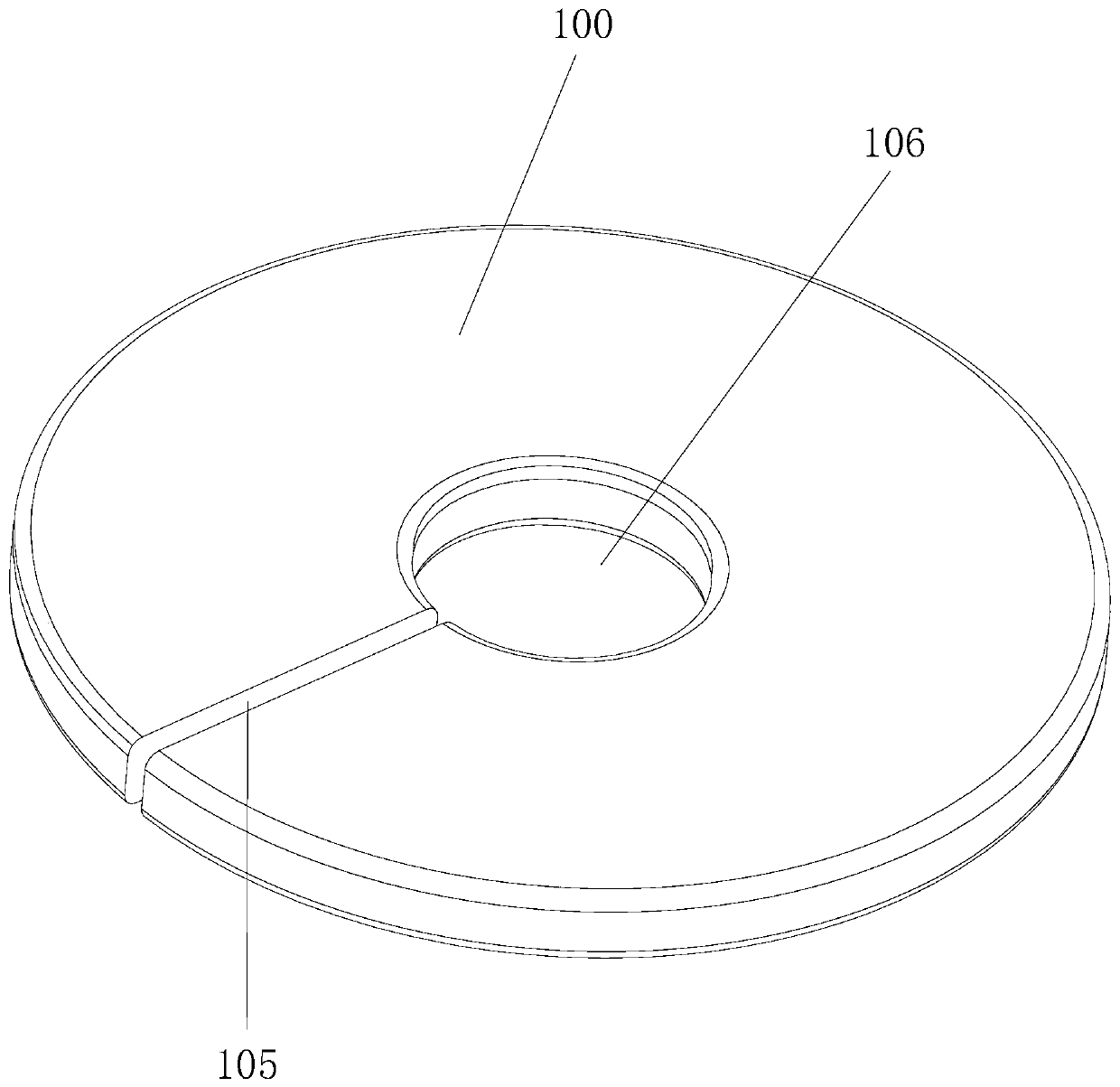
technical field [0001] The invention relates to a positioning system and a welding method for flange welding. Background technique [0002] In the field of welding technology, there are various welding methods, such as laser welding and telephone welding. For circular workpieces, such as flanges, arc welding is often used. The welding seam on the flange generally extends along the radial direction of the flange and passes through the flange, while the opposite sides of the welding seam are uneven, that is, they are misaligned in the axial direction. Therefore, when welding, on the one hand, it is necessary to use the first jig to clamp the flange so that the weld width of the flange becomes smaller; on the other hand, it is necessary to use the second jig to compress the flange. flange, so that the opposite sides of the weld are aligned in the axial direction, and the positioning of the flange can be achieved by using two jigs to act successively. However, the shrinkage a...

Claims


Application Information

Patent Timeline
Patent Type & Authority Applications(China)
IPC IPC(8): B23K37/04B23K9/32B23K9/02
CPCB23K9/02B23K9/32B23K37/04B23K37/0443
Inventor 陈佳佳
Owner 唐山文丰重工有限公司
Why Eureka
Try Eureka