Hydraulic engineering sludge pipeline dredging device

A technology for water conservancy projects and sludge, which is applied in the field of dredging equipment for sludge pipelines in water conservancy projects, can solve problems such as blockage and reduced pipe diameter, and achieve the effect of preventing shaking

Active Publication Date: 2020-04-21
嘉兴华竹电子有限公司
View PDF7 Cites 2 Cited by
  • Summary
  • Abstract
  • Description
  • Claims
  • Application Information

AI Technical Summary

Problems solved by technology

[0002] During the construction of water conservancy projects, pipelines are often used to transport the sludge in the river. The sludge contains different sundries, especially some plant fibers and plastic bags, which will be mixed with the sludge to form Agglomeration, these agglomerates enter some small-diameter pipes, and will adhere to the inner wall of the pipe, causing the pipe diameter to become smaller. Over time, it is prone to internal blockage and needs to be cleaned regularly

Method used


Image

  • Hydraulic engineering sludge pipeline dredging device
  • Hydraulic engineering sludge pipeline dredging device
  • Hydraulic engineering sludge pipeline dredging device

Examples


Embodiment 1

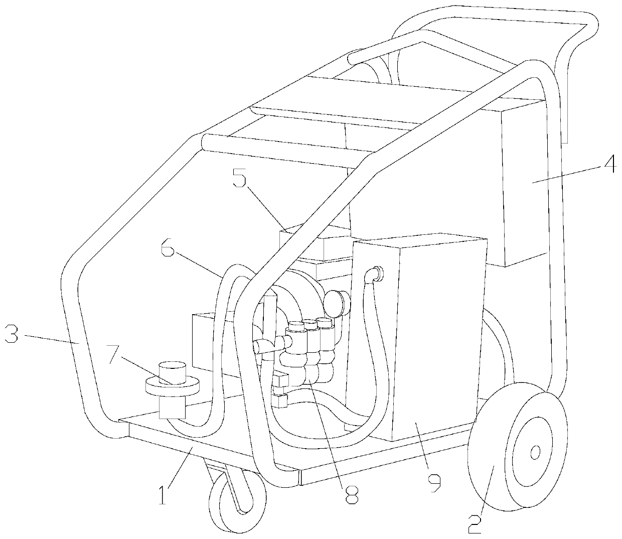
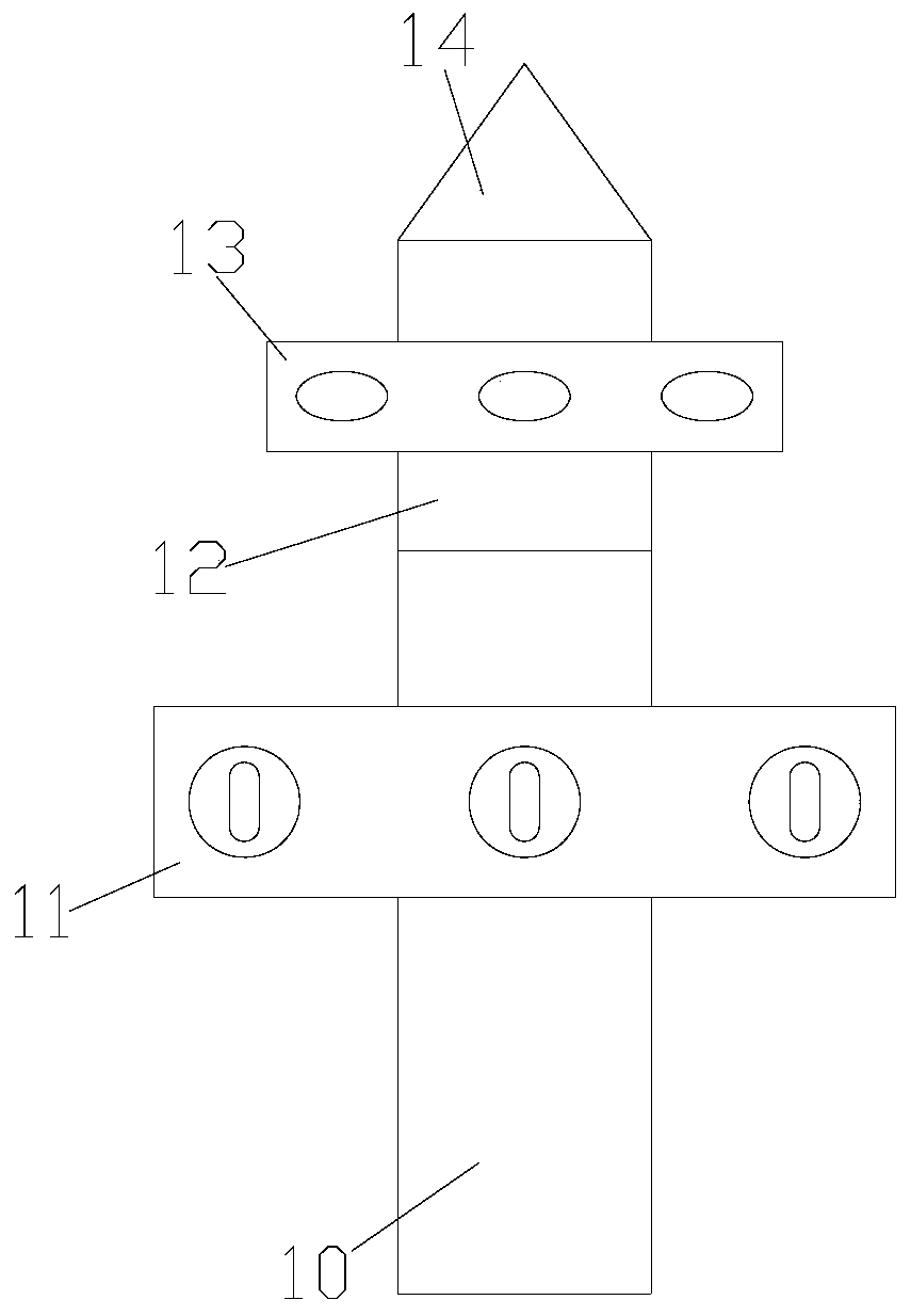
[0024] see Figure 1-Figure 4 , the present invention provides a technical solution for dredging equipment for sludge pipelines in hydraulic projects: its structure includes a bottom plate 1, a moving wheel 2, a protective frame 3, a power box 4, a power machine 5, a gas pipe 6, a dredging mechanism 7, a valve 8, and a pressure box 9 , the bottom of the bottom plate 1 is equipped with a moving wheel 2 and a protective frame 3 is welded above the top, the power supply box 4 is installed on the protective frame 3 and is electrically connected with the power machine 5, and the power machine 5 and the pressure box are installed on the bottom plate 1 9. The pressure tank 9 is connected to the power machine 5 through the valve 8, the dredging mechanism 7 is connected to the valve 8 through the air pipe 6, and the dredging mechanism 7 is composed of a connecting pipe 10, a stabilizing device 11, a rotator 12, The device 13 and the cone head 14 are composed. The connecting pipe 10 is ...

Embodiment 2

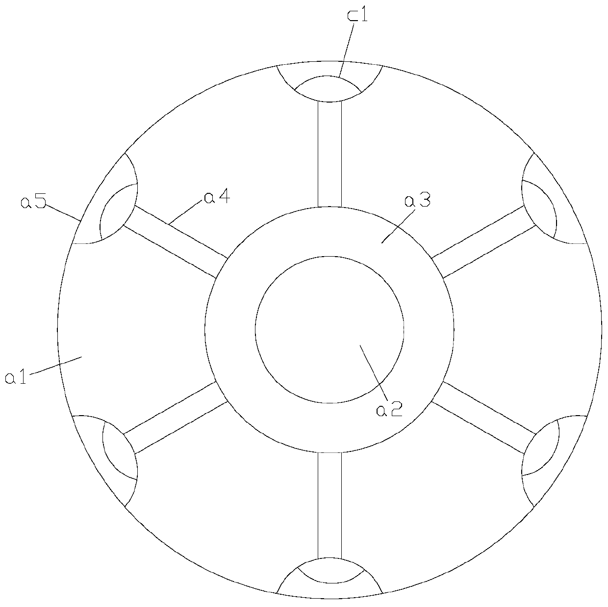
[0027] Such as Figure 5 As shown, on the basis of Embodiment 1, it is also included that the stabilizing device 11 is composed of a support plate b1, a jack b2, and an air inlet b3, the middle of the support plate b1 is connected with the air intake pipe a2, and the support There are six sets of jacks b2 on the disk b1, the bottom of the jacks b2 is connected to the intake pipe a2 through the air inlet b3, and the jacks b2 are composed of telescopic cylinder e1, push rod e2, pulley e3 , arc-shaped groove e4, the telescopic cylinder e1 is provided with a top push rod e2, and the end surface of the push rod e2 away from the telescopic cylinder e1 has an arc-shaped groove e4 and a pulley e3 is installed inside the arc-shaped groove e4 .

[0028] Before the screw breaking device 13 breaks up the sludge, the high-pressure airflow enters the intake pipe a2, a part of the airflow of the intake pipe a2 enters the jack b2 through the air inlet b3, and the telescopic cylinder e1 in th...


PUM


Abstract

The invention discloses a hydraulic engineering sludge pipeline dredging device. The hydraulic engineering sludge pipeline dredging device structurally comprises a bottom plate, moving wheels, a protective frame, a power box, a power machine, an air pipe, a dredging mechanism, a valve and a pressure box, wherein the moving wheels are mounted at the bottom of the bottom plate, and the protective frame is welded above the top of the bottom plate; the power box is mounted on the protective frame and electrically connected with the power machine; the power machine and the pressure box are mountedon the bottom plate; and the pressure box is connected with the power machine through the valve. The hydraulic engineering sludge pipeline dredging device has the beneficial effects that six groups ofexpansion bags are arranged on a rotating disc, conical teeth are arranged on the expansion bags, the expansion bags expand under the action of airflow, the conical teeth are driven to prick into sludge cakes, and the cakes are rapidly disintegrated; and a stabilizing device is mounted at the bottom of a rotary breaking device, in a telescopic cylinder in the stabilizing device, the telescopic cylinder drives a pulley on a pushing rod to extend outwards to be attached to the inner wall of a pipeline under the action of air pressure, so that the dredging mechanism plays a stabilizing role whenthe sludge cakes are conducted, and the shaking phenomenon is prevented.

Description

technical field [0001] The invention relates to dredging equipment for sludge pipelines in water conservancy projects, and belongs to the technical field of pipeline dredging equipment. Background technique [0002] During the construction of water conservancy projects, pipelines are often used to transport the sludge in the river. The sludge contains different sundries, especially some plant fibers and plastic bags, which will be mixed with the sludge to form Agglomeration, these agglomerates enter some small-diameter pipes, and will adhere to the inner wall of the pipe, causing the pipe diameter to become smaller. Over time, it is prone to internal clogging and needs to be cleaned regularly. Contents of the invention [0003] Aiming at the deficiencies in the prior art, the purpose of the present invention is to provide a dredging equipment for hydraulic engineering sludge pipelines to solve the problems. [0004] In order to achieve the above object, the present invent...

Claims


Application Information

Patent Timeline
IPC IPC(8): E03F7/10E03F9/00
CPCE03F7/10E03F9/002
Inventor 雷谢明
Owner 嘉兴华竹电子有限公司
Why Eureka
Try Eureka