
A Construction Method for Vertically Exposed Aggregate Concrete Wall

A concrete wall and construction method technology, applied in the processing of building materials, construction, building construction, etc., can solve the problems of easy cracking and falling off, easy falling off, difficult to control the pouring process, etc., so as to achieve the goal of not easy cracking and falling off, and ensure the overall strength , The effect of saving construction time

Active Publication Date: 2021-08-10
金蓉
View PDF7 Cites 0 Cited by
  • Summary
  • Abstract
  • Description
  • Claims
  • Application Information

AI Technical Summary

Problems solved by technology

This kind of wall panel manufacturing method has the following defects: (1) make wall panels on the ground (plane construction), and then install the wall panels on the wall, the overall construction period is long, easy to fall off, and the area of ​​the wall panels cannot If it is too large, there are many joints; (2) The pouring period of the wallboard is long; it is necessary to wait for a period of time after the initial setting of the colored exposed aggregate concrete layer to pour the ordinary concrete, so as to avoid the excessive fusion of the colored concrete and the ordinary concrete; (3) The pouring process is difficult to control; if the colored concrete with exposed aggregates solidifies for too short a time and ordinary concrete is poured, the two types of concrete will be too blended and the color effect will be affected; The bonding surface of the concrete is not firm, and the wall is installed vertically. After a long time of use, the two kinds of concrete will separate or fall off.
This method takes a long time and is costly when pouring exposed aggregate concrete on the formed wall, and the exposed aggregate concrete on the surface layer is easy to crack and fall off between the printed wall

Method used


Image

  • A Construction Method for Vertically Exposed Aggregate Concrete Wall
  • A Construction Method for Vertically Exposed Aggregate Concrete Wall

Examples


Embodiment Construction

[0036] The following will clearly and completely describe the technical solutions in the embodiments of the present invention with reference to the accompanying drawings in the embodiments of the present invention. Obviously, the described embodiments are only some, not all, embodiments of the present invention. Based on the embodiments of the present invention, all other embodiments obtained by persons of ordinary skill in the art without making creative efforts belong to the protection scope of the present invention.

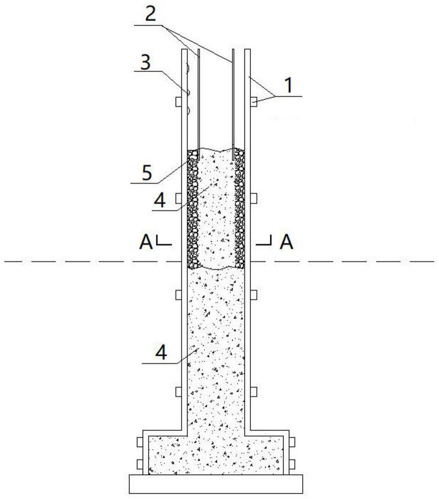
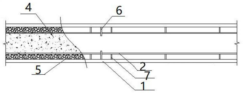
[0037] Please refer to figure 1 and figure 2 , the present embodiment provides a construction method for a vertically exposed aggregate concrete wall, which specifically includes the following steps:

[0038] Step 1, supporting the pouring formwork 1; the pouring formwork 1 can be a wooden formwork, an aluminum formwork or a steel formwork, and is used to shape the concrete pouring.

[0039] Step 2: Bind steel bars in the pouring cavity of the pouring formw...


PUM


Abstract

The invention discloses a construction method for a concrete wall with exposed aggregate on the vertical surface, which comprises the following steps: S1, supporting the pouring formwork; S2, making a pouring partition; the pouring partition is made of a high-strength metal material with a smooth surface; S3, installing Pouring partitions; before pouring, place the pouring partitions vertically in the pouring cavity of the pouring formwork, and the two sides of the pouring partitions form mutually independent exposed aggregate concrete pouring cavities and ordinary concrete pouring cavities; S4, pouring concrete; first Pouring concrete with exposed aggregate, and then pouring ordinary concrete; S5. After the initial setting of ordinary concrete, pull out the pouring partition upwards. During the process of pulling up the partition, tap the outer wall of the pouring formwork to improve the bonding between exposed aggregate concrete and ordinary concrete. Surface Fusion. The invention pours ordinary concrete in the inner layer and fills the exposed aggregate concrete on the surface, so that the concrete wall can present rich texture and color effects without secondary decoration, and at the same time, the inner and outer layer concrete is not easy to crack and fall off.

Description

technical field [0001] The invention belongs to the technical field of decorative concrete wall construction, and in particular relates to a construction method for a vertically exposed aggregate concrete wall. Background technique [0002] The exposed aggregate concrete body originated in the 1970s and was applied in China at the beginning of this century. In recent years, it has been widely used in road paving and urban squares. It has high durability, one-time molding, no need for secondary decoration, and water permeability. Good characteristics, is a good ground paving material. [0003] At present, exposed aggregate concrete is affected by the technology, and it is mostly used in plane paving projects, but less in vertical walls, and its application range is limited to a certain extent. Compared with fair-faced concrete walls, exposed concrete walls have the characteristics of rich colors and textures. [0004] The Chinese invention patent with the patent number of 2...

Claims


Application Information

Patent Timeline
Patent Type & Authority Patents(China)
IPC IPC(8): E04G21/00
CPCE04G21/00
Inventor 金蓉邹梦宬代琦
Owner 金蓉
Learn More