3D camera simulation debugging equipment

A camera and equipment technology, applied in the field of 3D camera simulation and debugging equipment, can solve the problems of not being able to design multiple 3D cameras, not being able to directly obtain lasers and camera modules, etc.

Active Publication Date: 2020-04-21
GUANGZHOU RUISONG INTELLIGENT TECH CO LTD
View PDF4 Cites 1 Cited by
  • Summary
  • Abstract
  • Description
  • Claims
  • Application Information

AI Technical Summary

Problems solved by technology

[0003] When designing a 3D camera, it is necessary to have a device that can fix the laser and the camera module, and adjust the positions of the fixed laser and camera, so as to simulate the lasers and camera modules inside a variety of 3D cameras for different items The positional relationship between the laser and the camera is to build a 3D analog camera. At this time, the relative position distance and angle between the laser and the camera can be intuitively known, and then the design of the 3D camera can be realized; however, when detecting different items, when replacing the camera After the camera and the laser are adjusted, the positions of the camera and the laser need to be readjusted. After the camera or the laser is adjusted in a certain direction, the existing device cannot directly confirm how the adjusted current position changes from the position before the adjustment, so it cannot be obtained directly. The relative position between the adjusted laser and the camera module in a certain direction cannot be designed for various 3D cameras

Method used


Image

  • 3D camera simulation debugging equipment
  • 3D camera simulation debugging equipment
  • 3D camera simulation debugging equipment

Examples


Embodiment Construction

[0045] Below, the present invention will be further described in conjunction with the accompanying drawings and specific implementation methods. It should be noted that, on the premise of not conflicting, the various embodiments described below or the technical features can be combined arbitrarily to form new embodiments. .

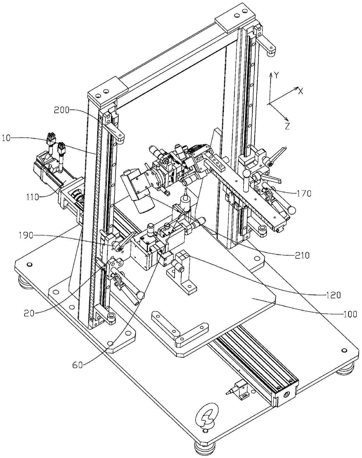
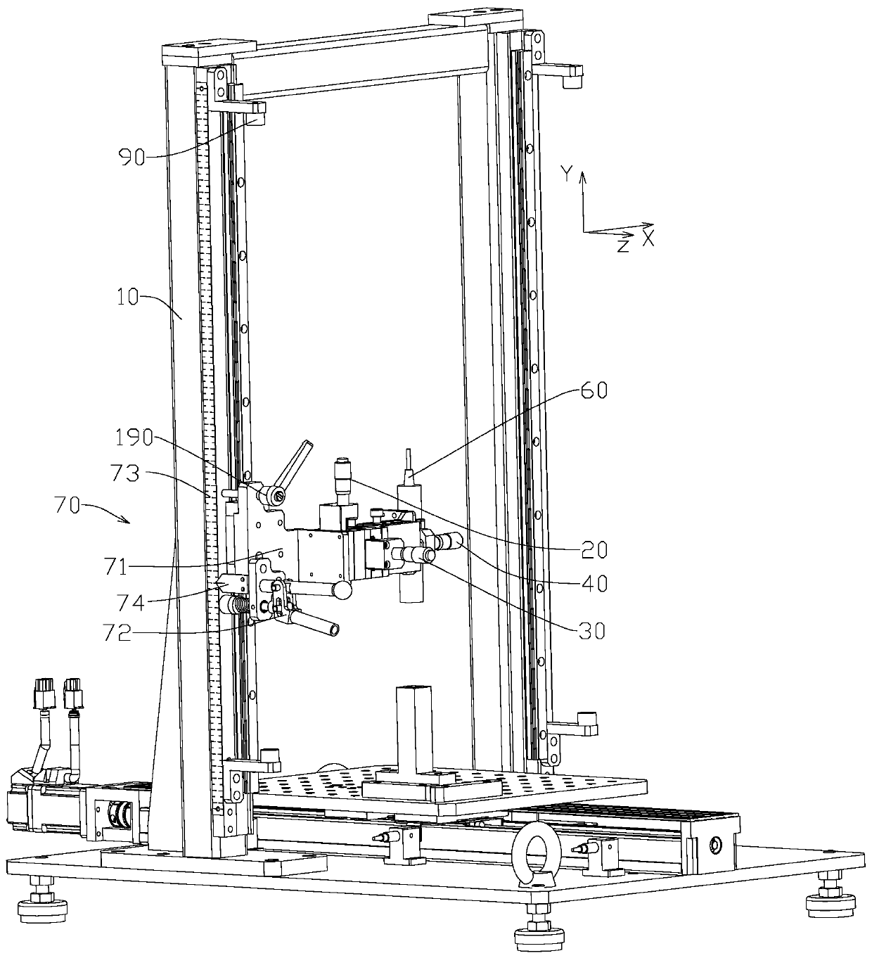
[0046] Such as Figure 1-3 as well as Figure 6-7 A 3D camera simulation debugging device shown includes a support 10, a first Y-direction coarse adjustment mechanism 70, a laser mounting base 50, a second Y-direction coarse adjustment mechanism 80, an imaging mounting base 90 and a detection platform 100; wherein,

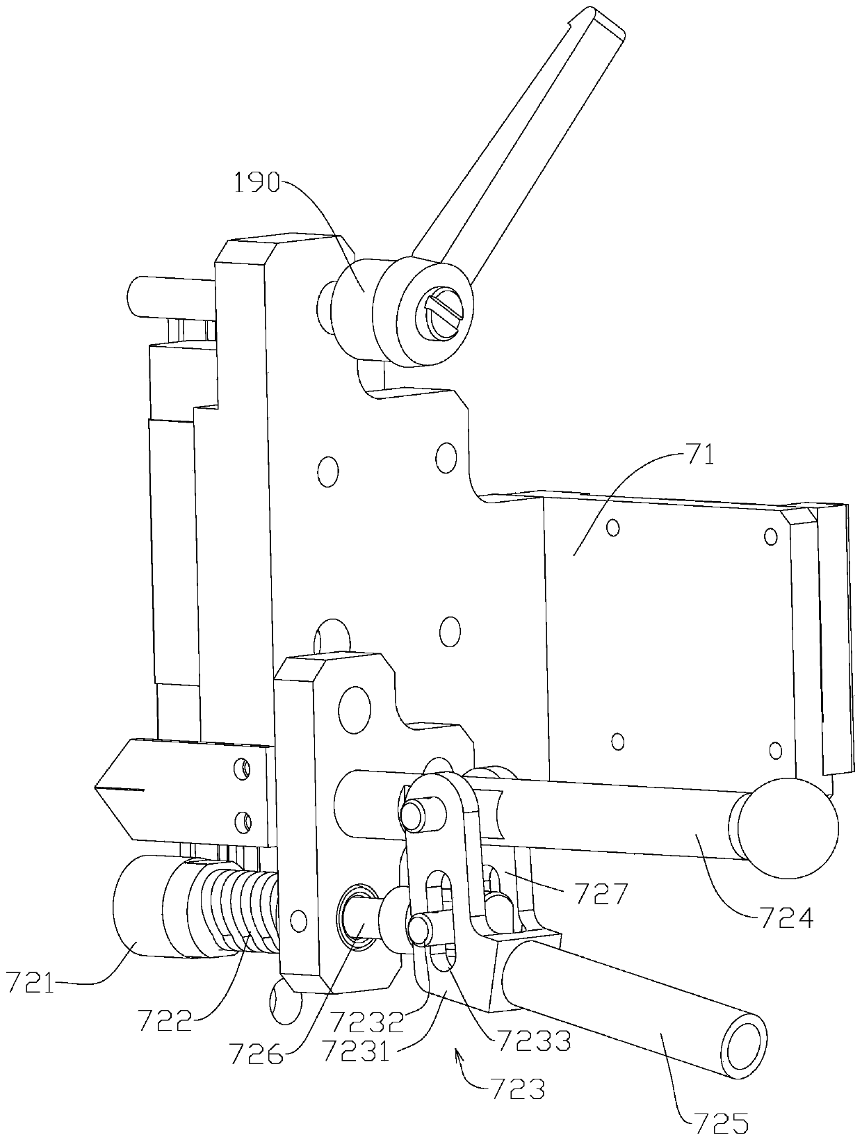
[0047] The first Y direction coarse adjustment mechanism 70 includes a first sliding seat 71 and a first elastic structure 72; the first sliding seat 71 is installed on the support 10, and can move relative to the support 10 along the Y direction; the support 10 is provided with A first scale scale 73 that extends along the Y direction and ...


PUM


Abstract

The invention discloses 3D camera simulation debugging equipment. The 3D camera simulation debugging equipment comprises a support, a first Y-direction coarse adjustment mechanism, a second Y-direction coarse adjustment mechanism and a detection platform installed on the support; the first Y-direction coarse adjustment mechanism comprises a first sliding seat and a first elastic structure; the first sliding seat can be mounted on the support in a manner of moving relative to the support in the Y direction; a first graduated scale is arranged on the support; a first indicating arrow pointing tothe graduated scale is mounted on the first sliding seat, and a laser mounting seat for mounting a laser is fixed on the first sliding seat; the second Y-direction coarse adjustment mechanism comprises a second sliding seat and a second elastic structure; the second sliding seat can be mounted on the support in a manner of moving relative to the support in the Y direction; the support is providedwith a second graduated scale; and the second sliding seat is provided with a second indicating arrow pointing to the second graduated scale and a camera mounting seat for mounting a camera module. According to the 3D camera simulation debugging equipment, multi-dimensional adjustment of the relative positions of the laser and the camera module in the Y direction can be realized so as to be suitable for the design of various 3D cameras.

Description

technical field [0001] The invention relates to a debugging device, in particular to a 3D camera simulation debugging device. Background technique [0002] At present, in the application of domestic industrial 3D vision technology, 3D cameras are used to obtain three-dimensional images of objects. When in use, the 3D camera forms a triangular relationship with the measured object through its internal camera module and internal laser. After that, the laser irradiates structured light On the object to be detected, the camera module receives the structured light reflected by the object to be detected to obtain a 3D image; wherein, the quality of the 3D image is determined by the positional relationship between the laser and the camera module, and the position between the laser and the camera module After the relationship is fixed, it can only obtain a clear 3D image of one item. [0003] When designing a 3D camera, it is necessary to have a device that can fix the laser and ca...

Claims


Application Information

Patent Timeline
IPC IPC(8): F16M11/04F16M11/10F16M11/16F16M11/18F16M11/20H04N13/296
CPCF16M11/045F16M11/046F16M11/048F16M11/10F16M11/16F16M11/18F16M11/20H04N13/296F16M2200/027F16M2200/028F16M2200/04
Inventor 李志成何艳兵刘尔彬吴晓杰袁然
Owner GUANGZHOU RUISONG INTELLIGENT TECH CO LTD
Why Eureka
Try Eureka