
Toilet airflow exchange equipment for preventing corrosion of circuit components

A technology of airflow exchange and circuit components, which is applied in the field of toilet airflow exchange, can solve the problems of inability to distinguish between dry and wet air, rust increases leakage, affects quality of life, etc., and achieves the effect of reducing the risk of rust leakage

Inactive Publication Date: 2020-04-21
义乌程祺电子商务有限公司
View PDF0 Cites 0 Cited by
  • Summary
  • Abstract
  • Description
  • Claims
  • Application Information

AI Technical Summary

Problems solved by technology

[0003] And because the toilet is a dry-wet junction place, the humidity in the air is relatively high, the traditional ventilation equipment can only produce suction, but cannot carry out differential suction of dry and wet air, resulting in the air with high humidity entering the ventilation equipment After that, it accumulates on the surface of circuit components, which will increase the risk of leakage due to its corrosion over time; in addition, due to the difference in flow rate and quality of dry and wet airflow, traditional ventilation equipment can only use the same suction force to suck both , so the suction effect can be imagined, which indirectly affects people's quality of life, so a kind of toilet air exchange equipment to prevent the corrosion of circuit components came into being

Method used


Image

  • Toilet airflow exchange equipment for preventing corrosion of circuit components
  • Toilet airflow exchange equipment for preventing corrosion of circuit components
  • Toilet airflow exchange equipment for preventing corrosion of circuit components

Examples


Embodiment Construction

[0024] The technical solutions in the embodiments of the present invention will be clearly and completely described below in conjunction with the accompanying drawings in the embodiments of the present invention. Obviously, the described embodiments are only a part of the embodiments of the present invention, rather than all the embodiments. Based on the embodiments of the present invention, all other embodiments obtained by those of ordinary skill in the art without creative work shall fall within the protection scope of the present invention.

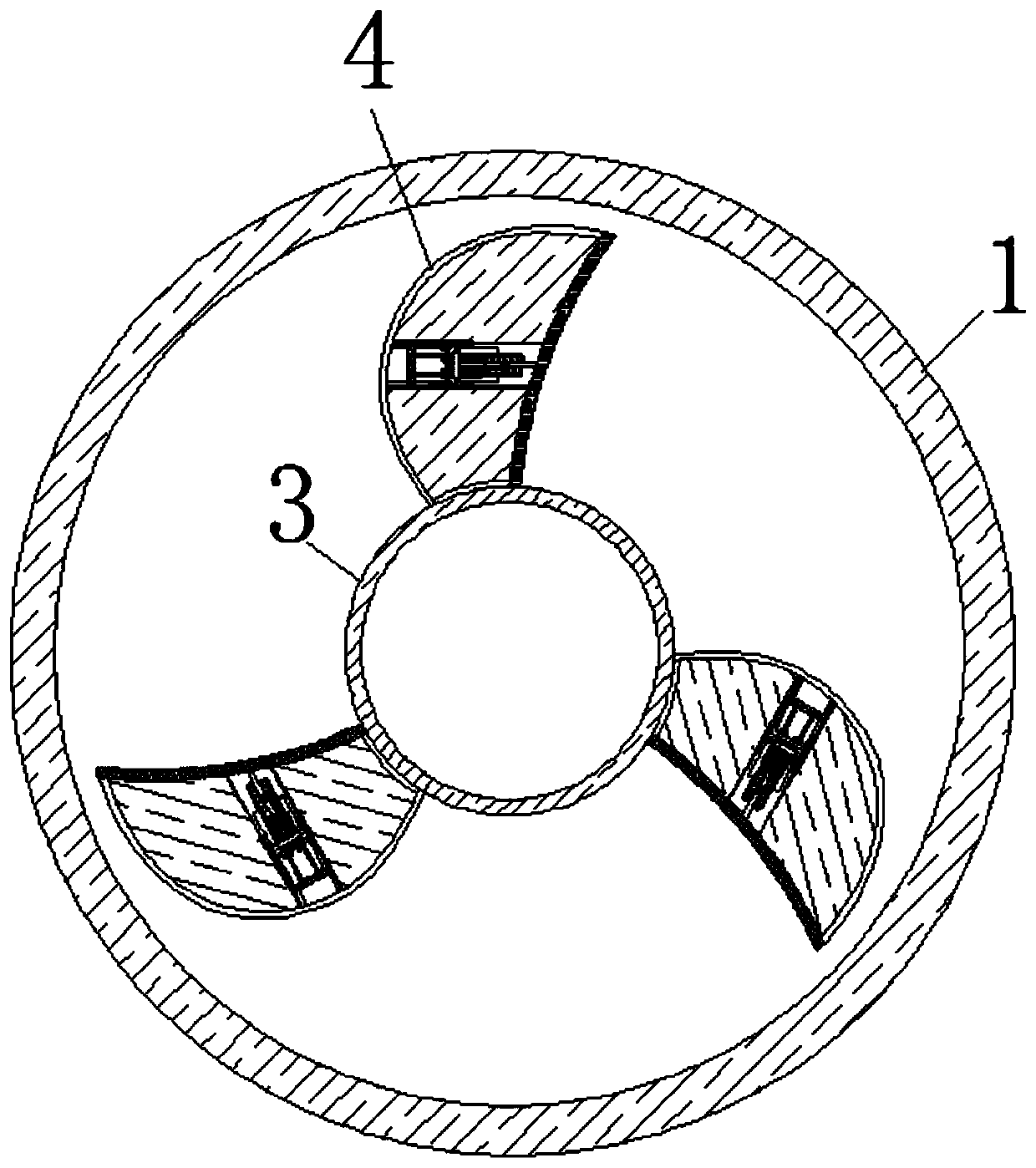
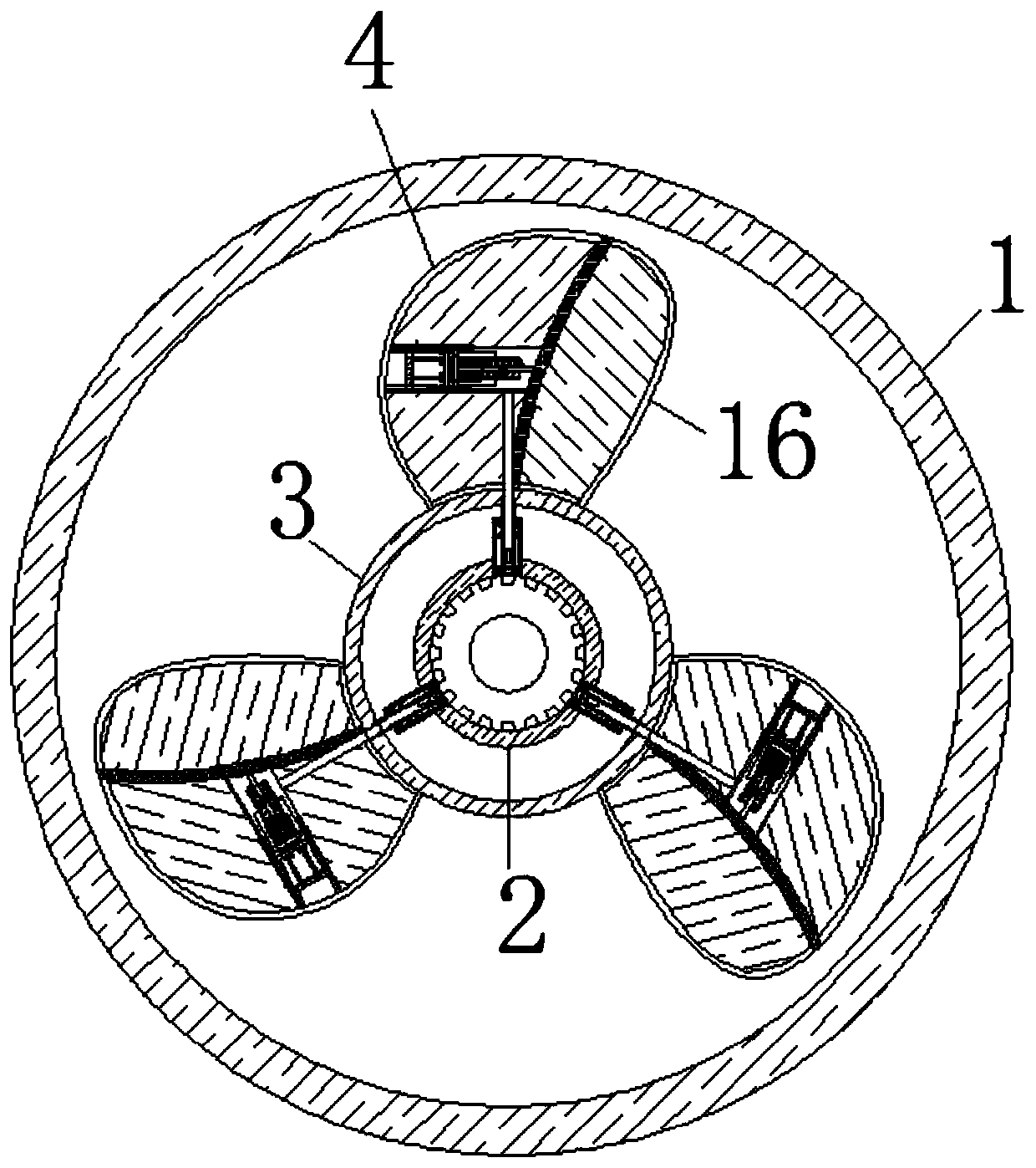
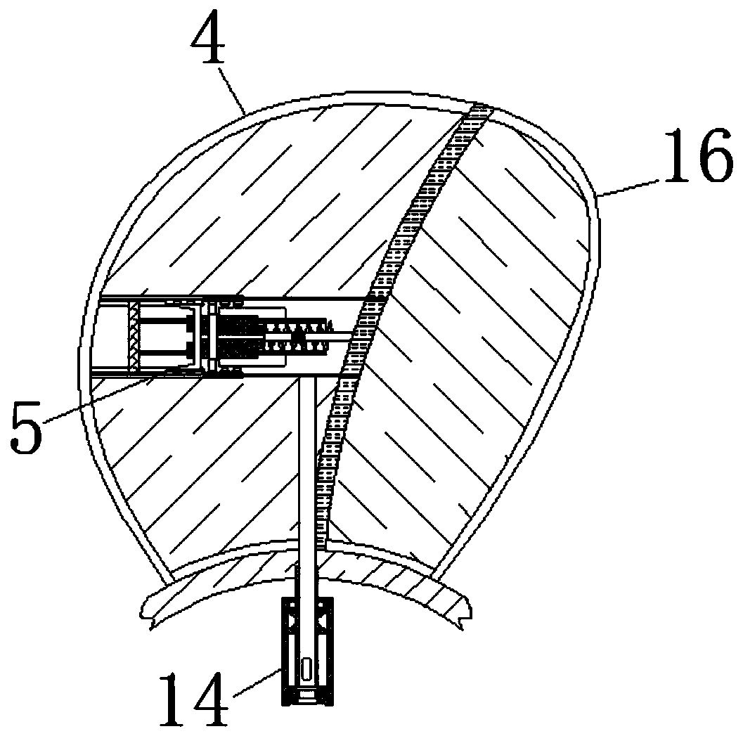
[0025] See Figure 1-7 , A toilet air exchange equipment to prevent corrosion of circuit components, including a pipe 1. The pipe 1 is movably connected with a rotating shaft 2, and the rotating shaft 2 plays a role of providing original power. The surface of the rotating shaft 2 is movably connected with a gear 3, which is connected with A water storage rod 14 is fixedly connected to the connection of the rotating shaft 2, and the water...


PUM


Abstract

The invention relates to the technical field of toilet airflow exchange, and discloses toilet airflow exchange equipment for preventing corrosion of circuit components. The toilet airflow exchange equipment for preventing corrosion of the circuit components comprises a pipeline, wherein the interior of the pipeline is movably connected with a rotating shaft, the surface of the rotating shaft is movably connected with a gear, the surface of the gear is fixedly connected with a fan blade, the interior of the fan blade is movably connected with an expanding and contracting piece, the interior ofthe expanding and contracting piece is fixedly connected with a sliding rail, the surface of the sliding rail is slidably connected with a bearing plate, therefore, the bearing plate is pulled on thesurface of the sliding rail to push a filling plate out as shown in figure 2, at the moment, the whole area of the fan blade becomes larger, the adhesion surface of the water vapor quenched into liquid becomes larger, and then the same movement is generated and drained into a water storage rod, so that the effect of capturing and draining the airflow with higher humidity and reducing the risk of corrosion and electric leakage is achieved; a friction block can be in contact with the rotating shaft, the meshing force between the gear and the rotating shaft is increased, and the phenomenon that the rotating shaft and the gear are not stably engaged due to the increase of the fan blade is avoided.

Description

Technical field [0001] The invention relates to the technical field of toilet air exchange, in particular to a toilet air exchange equipment for preventing corrosion of circuit components. Background technique [0002] With the development of science and technology, people’s daily life is becoming more and more convenient, and the quality of life is getting higher and higher. Among them, the air quality of the toilet has gradually attracted people’s attention. For this reason, people have produced ventilating equipment, which is produced by the rotation of worm gears. The air is sucked to guide the toilet air to the outside, and then play the role of air exchange. [0003] However, because the toilet is a place where wet and dry are connected, the humidity in the air is relatively high. The traditional ventilation equipment can only produce suction instead of differently sucking dry and wet air, resulting in a humidified airflow entering the ventilation equipment. Later, it accumu...

Claims


Application Information

Patent Timeline
Patent Type & Authority Applications(China)
IPC IPC(8): F24F7/06F24F11/74F24F110/20
CPCF24F7/065F24F11/74F24F2110/20
Inventor 许飞云
Owner 义乌程祺电子商务有限公司
Learn More