
Test piece anti-icing air entraining flow device and test method

A technology of test pieces and air flow, applied in the field of test systems, to achieve the effect of simple structure, accurate data, and low difficulty in realizing the process

Active Publication Date: 2020-04-21
湖南汉能科技有限公司
View PDF6 Cites 5 Cited by
  • Summary
  • Abstract
  • Description
  • Claims
  • Application Information

AI Technical Summary

Problems solved by technology

At present, there is a lack of test devices that can accurately simulate the deicing bleed air system during flight of aeroengines

Method used


Image

  • Test piece anti-icing air entraining flow device and test method
  • Test piece anti-icing air entraining flow device and test method
  • Test piece anti-icing air entraining flow device and test method

Examples


Embodiment 1

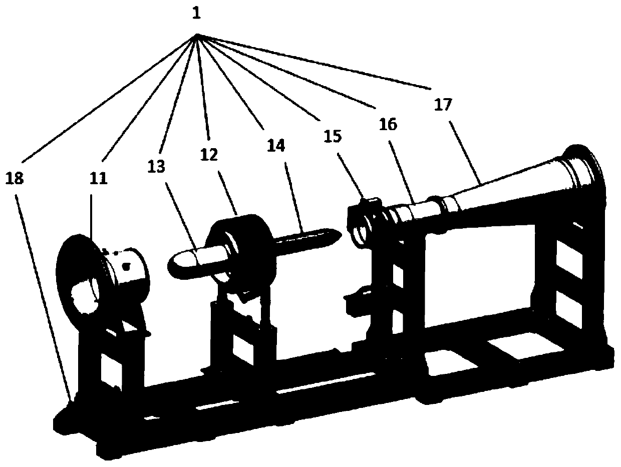
[0027] A test device for anti-icing of test pieces, such as figure 1 As shown, it includes a test piece installation system 1, a compressed air source system 2 and an exhaust pipe 3.

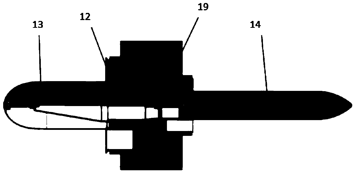
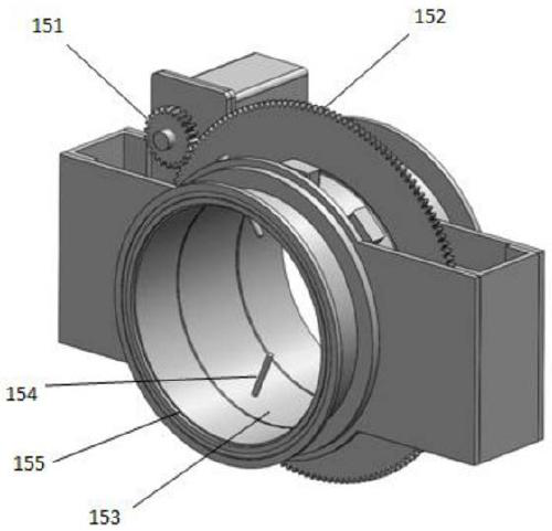
[0028] Such as figure 2 As shown, the test piece installation system 1 includes a test piece installation mechanism 12, an air intake shroud 11, an intake cone assembly 13, an exhaust cone assembly 14, an exhaust straight pipe 16, a rotating measuring mechanism 15 and an expansion section 17, and Install the mounting bracket 18 of the above-mentioned components. The intake shroud, the test piece installation mechanism 12, the rotating measuring mechanism 15, the exhaust straight pipe 16 and the expansion section 17 are sequentially connected to form a circular tubular shape, and the intake cone assembly 13 and the exhaust cone assembly 14 are arranged in the pipe. The fairing 11 at the front and the intake cone assembly 13 form an annular straight pipe section; the rear exhaust cone assembly ...

Embodiment 2

[0040] This embodiment provides a test method for anti-icing bleed air flow of a test piece, using the test device described in Embodiment 1. An eddy current casing (single piece) and a test piece assembly are installed on the test piece installation mechanism 12, and the system can test the assembly or the single piece.

[0041] 1. For the single-piece test, the air enters from the anti-icing bleed air inlet 192 of the vortex casing. The bleed air pressure of the test is two different states of 0.1MPa and 0.2MPa respectively. It is necessary to measure the eddy current casing under two bleed air pressures. The standard bleed air flow rate of a single piece (that is, the flow rate corresponding to sea level and standard atmospheric conditions), and record the measured value.

[0042] Proceed as follows:

[0043] Connect the front vortex casing bleed air interface 192 and the large anti-icing bleed pipe interface 191 with the anti-icing bleed air pipeline, and seal the front v...


PUM


Abstract

A test piece anti-icing air entraining flow device comprises a test piece installation system, a compressed air source system and an exhaust pipeline; and the test piece installation system comprisesan annular straight pipe section, a test piece installation mechanism, a rotary measurement mechanism, an exhaust straight pipe section and an expansion section which are connected in sequence. The annular straight pipe section comprises an air inlet fairing and an air inlet cone arranged inside. The test piece installation mechanism is used for installing a test piece; the rotary measurement mechanism and the exhaust straight pipe section are sequentially connected to form a straight pipe, an exhaust cone assembly is installed in the straight pipe, and the rotary measuring mechanism is provided with a total pressure probe and a static pressure measuring hole; the rear part of the straight exhaust pipe section is connected with an expansion section; a compressed air source system is connected with an anti-icing air entraining pipe connector of the test piece and comprises a compressor, an air storage tank, an air dryer, a filter and an adjusting valve which are connected through a pipeline. The exhaust pipeline is connected to the rear end of the test piece installation system. The device has the advantages of high test accuracy and real simulation environment.

Description

technical field [0001] The invention relates to a test system for aero-engine components, in particular to a particle separator test stand. Background technique [0002] In order to prevent icing during flight from endangering flight safety, an anti-icing system needs to be installed. In the existing aircraft anti-icing system, high-temperature hot air from the engine is used for anti-icing, which has the advantages of high reliability, good anti-icing performance, and simple structure. The principle is to lead high-temperature and high-pressure air from the high-pressure compressor of the engine, so that it enters the icing area of ​​the aircraft through the pipeline, and heats the skin surface to prevent the surface from icing. [0003] The anti-icing bleed air flow test is a special test to check the anti-icing bleed air capacity, and to test whether the anti-icing bleed air design of the aero-engine meets the requirements. At present, there is a lack of test devices tha...

Claims


Application Information

Patent Timeline
Patent Type & Authority Applications(China)
IPC IPC(8): G01M15/14G01M15/02
CPCG01M15/02G01M15/14
Inventor 廖利华郭斌
Owner 湖南汉能科技有限公司
Learn More