A working method of electron source

A working method and technology of electron source, applied in the field of electron source, can solve problems such as easy burning of CFE, low utilization rate, limited use range, etc.

Active Publication Date: 2021-04-27
CHINA ELECTRONIC TECH GRP CORP NO 38 RES INST
View PDF7 Cites 0 Cited by
  • Summary
  • Abstract
  • Description
  • Claims
  • Application Information

AI Technical Summary

Problems solved by technology

[0009] In the process of realizing the disclosed concept, the inventors have found that there are at least the following problems in CFE in the prior art: first, the stability of CFE is often poor, and it needs to be processed under extremely high vacuum (10 -9 ~10 -8 Pa) to work, which severely limits its use
Second, affected by ion bombardment, CFE is easier to burn
Third, the above-mentioned problems become more serious at higher emission currents. The existing CFEs generally can work stably for a long time with a total emission current of ~10 microamperes, and the utilization rate is very low.

Method used


Image

  • A working method of electron source
  • A working method of electron source
  • A working method of electron source

Examples


Embodiment Construction

[0045] Hereinafter, embodiments of the present disclosure will be described with reference to the drawings. It should be understood, however, that these descriptions are exemplary only, and are not intended to limit the scope of the present disclosure. In the following detailed description, for purposes of explanation, numerous specific details are set forth in order to provide a thorough understanding of the embodiments of the present disclosure. It may be evident, however, that one or more embodiments may be practiced without these specific details. Also, in the following description, descriptions of well-known structures and techniques are omitted to avoid unnecessarily obscuring the concept of the present disclosure.

[0046] The terminology used herein is for the purpose of describing particular embodiments only, and is not intended to be limiting of the present disclosure. The terms "comprising", "comprising", etc. used herein indicate the presence of stated features, ...


PUM


Abstract

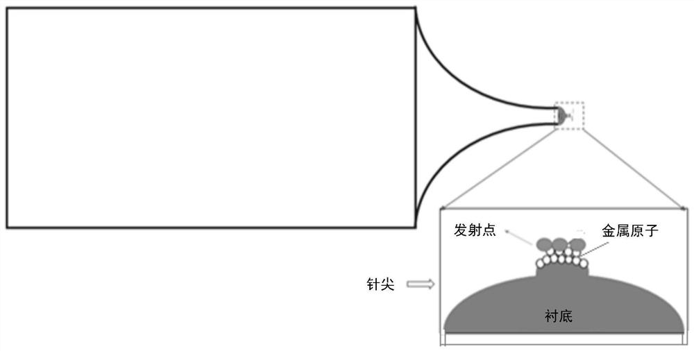
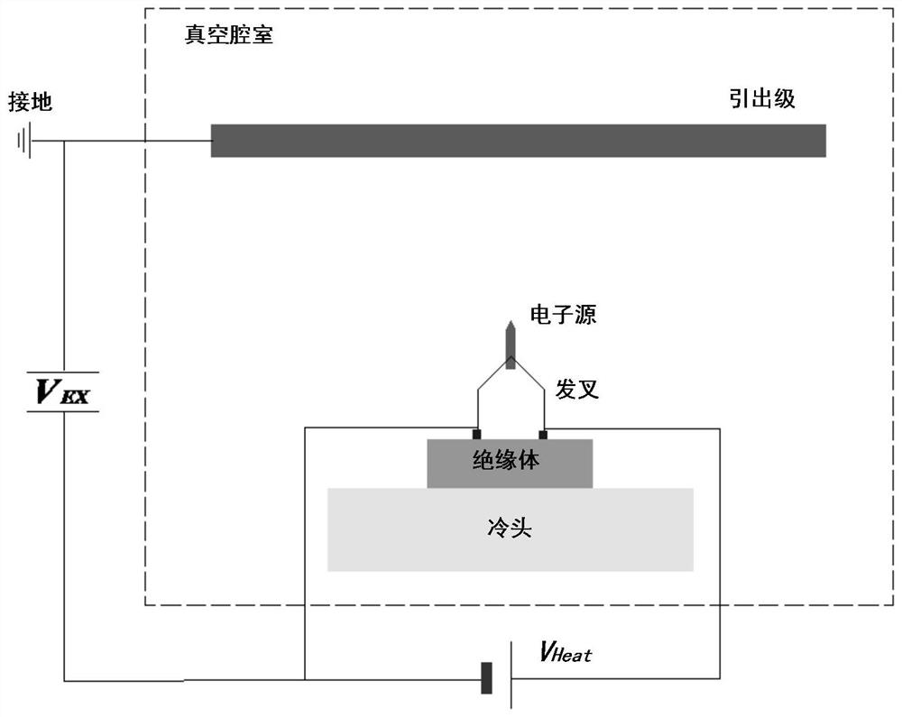
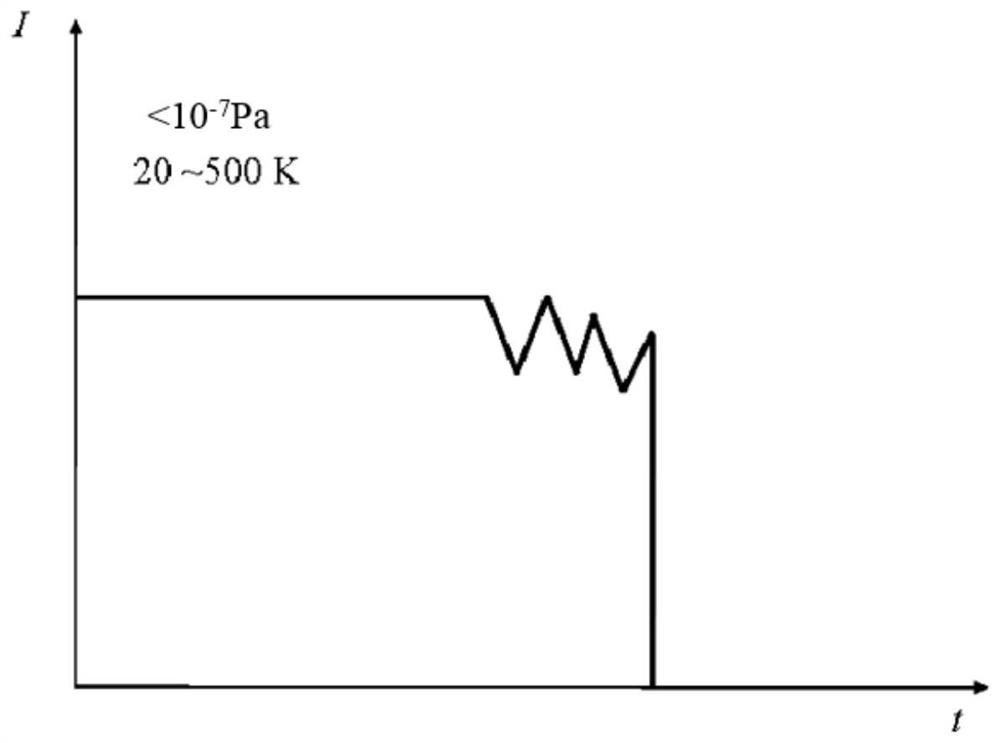
The present disclosure provides a working method of an electron source, the electron source includes at least one emission point fixed on the needle tip, the emission point is a reaction product formed by metal atoms on the surface of the needle point and gas molecules under an electric field, the work The method includes emitting electrons by controlling operating parameters of said electron source.

Description

technical field [0001] The present disclosure relates to the technical field of electron sources, and more specifically, the present disclosure relates to a working method of an electron source. Background technique [0002] The free electrons in the metal can be emitted under certain conditions. If the cathode is made of metal and made into a very thin needle point, and a voltage of thousands of volts is applied in a vacuum, the electrons in the metal can be emitted from the cathode cold metal. This method of emitting electrons is called field emission, which belongs to cold cathode emission. [0003] For the electron source, the most important indicator is the brightness, which directly determines the beam quality. Under the extraction voltage V0, the brightness can be shown as formula (1): [0004] [0005] Among them, B is the brightness, I is the emission current, S is the equivalent emission area, d is the equivalent diameter, Ω is the spatial emission angle, and ...

Claims


Application Information

Patent Timeline
Patent Type & Authority Patents(China)
IPC IPC(8): H01J3/02H01J1/304
CPCH01J3/022H01J1/3044H01J1/304H01J9/02H01J37/073H01J2237/06341H01J37/06
Inventor 刘华荣靳学明戚玉轩王学慧李艺晶王俊听郑春宁钱庆罗婷婷董中林
Owner CHINA ELECTRONIC TECH GRP CORP NO 38 RES INST
Why Eureka
Try Eureka