
High-isolation RF (radio frequency) switch circuit

A radio frequency switch, high isolation technology, applied in the field of high isolation radio frequency switch circuit, can solve the problem of radio frequency switch isolation decline, to avoid insertion loss and improve isolation effect

Active Publication Date: 2015-09-30
NO 24 RES INST OF CETC
View PDF4 Cites 6 Cited by
  • Summary
  • Abstract
  • Description
  • Claims
  • Application Information

AI Technical Summary

Problems solved by technology

[0006] Aiming at the technical problem in the prior art that the radio frequency switch introduces parasitic inductance to the ground bonding wire, resulting in a decrease in the isolation of the radio frequency switch, the present invention provides a high isolation radio frequency switch circuit, which is formed by connecting the radio frequency switch to the ground bonding wire The parasitic inductance of the filter is constructed as part of the filter, so that the isolation of the RF switch is improved

Method used


Image

  • High-isolation RF (radio frequency) switch circuit
  • High-isolation RF (radio frequency) switch circuit
  • High-isolation RF (radio frequency) switch circuit

Examples


Embodiment Construction

[0020] In order to make the technical means, creative features, goals and effects achieved by the present invention easy to understand, the present invention will be further described below in conjunction with specific illustrations.

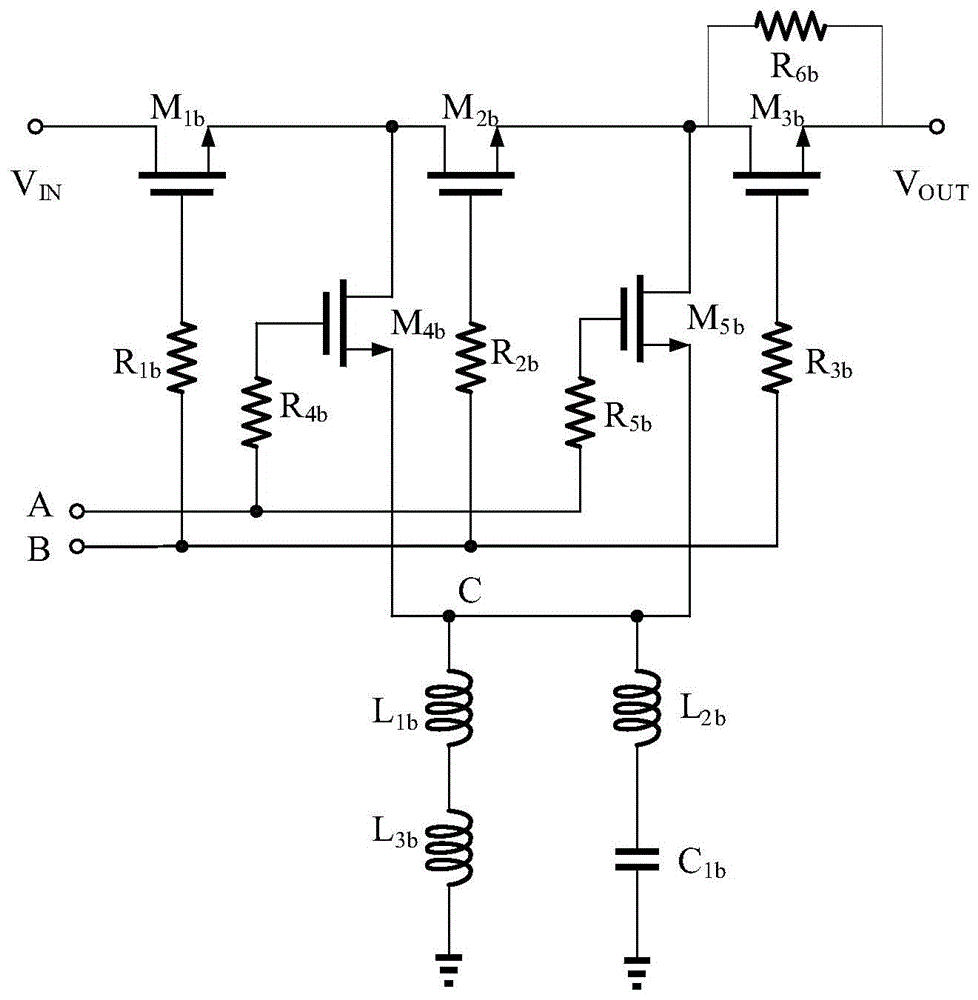
[0021] Please refer to figure 2 As shown, the present invention provides a high-isolation radio frequency switch circuit, including a basic single-pole single-throw radio frequency switch unit and a filter unit; wherein,

[0022] The basic single-pole single-throw radio frequency switch unit includes an NMOS transistor M 1b , NMOS tube M 2b , NMOS tube M 3b , NMOS tube M 4b , NMOS tube M 5b , resistance R 1b , resistance R 2b , resistance R 3b , resistance R 4b , resistance R 5b and resistor R 6b , the NMOS tube M 1b The drain of the signal input terminal V IN Connected, NMOS tube M 1b The source and NMOS tube M 2b and NMOS tube M 4b The drain is connected, the NMOS transistor M 2b The source and NMOS tube M 3b and NMOS tube M ...


PUM


Abstract

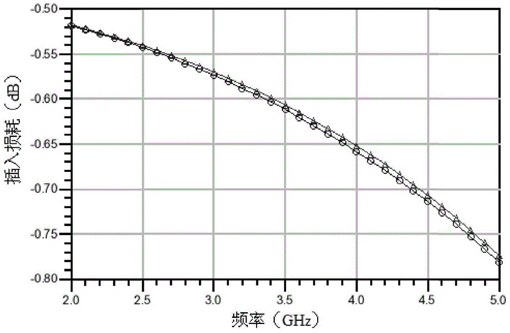
The invention provides a high-isolation RF (radio frequency) switch circuit. The circuit comprises a basic single-pole single-throw RF switch unit and a filter unit, wherein at a reference ground point C of the basic single-pole single-throw RF switch unit, a bonding wire parasitic inductor L1b is in series connection with an inductor L3b connected with the ground, a direct current channel is formed, a bonding wire parasitic inductor L2b is in series connection with a capacitor C1b connected with the ground, the inductor L1b is in series connection with an inductor L3b which is in parallel connection with the capacitor C1b connected with the reference ground point C through a bonding wire L2b, and a filter is formed. Thus, under the condition that the direct current channel from an RF switch to the ground is not affected, the bonding wire parasitic inductor L1b is integrated into the filter, the effect caused by bonding wire parasitic parameters on the isolation of the RF switch is reduced, the isolation of the RF switch at different frequencies can be increased in a targeted manner through adjustment of values of the inductor L3b and the capacitor C1b of the filter. The isolation of the high-isolation RF switch can be 5-10 dB higher than that of a traditional RF switch, and meanwhile, electrical characteristics such as insertion loss and the like of the RF switch cannot be affected.

Description

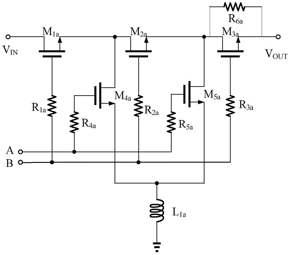
technical field [0001] The invention belongs to the field of radio frequency switches, in particular to a high isolation radio frequency switch circuit. Background technique [0002] The RF switch is a key unit in the RF signal processing system, widely used in radar and communication systems, and its performance directly determines the performance of the RF signal processing system. RF switches have been widely used due to their wide operating frequency bandwidth, low insertion loss, short switching time, and easy integration. [0003] Traditional RF switching circuits such as figure 1 As shown, due to the limitations of the commonly used CMOS / BiCMOS process, the reference ground of the RF switch needs to be connected to the ground through bonding wires, and the smaller the parasitic parameters between the reference ground and the ground connection of the RF switch, the greater the impact on the performance of the RF switch. the smaller the impact. However, in practical ...

Claims


Application Information

Patent Timeline
Patent Type & Authority Applications(China)
IPC IPC(8): H03K17/687
Inventor 刘成鹏王国强何峥嵘邹伟蒲颜
Owner NO 24 RES INST OF CETC
Learn More