Clamping control inertial impact motor
An inertial impact and clamping technology, applied in the field of precision drive and positioning, can solve the problems of low output force or torque, low speed of impact motor, weak load capacity, etc., and achieve small energy loss, large driving stroke and strong compression resistance effect of ability
- Summary
- Abstract
- Description
- Claims
- Application Information
AI Technical Summary
Problems solved by technology
Method used
Image

Examples
Embodiment Construction
[0039] The present invention will be further described through the embodiments below in conjunction with the accompanying drawings.
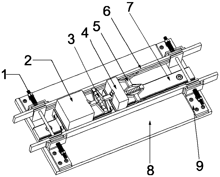
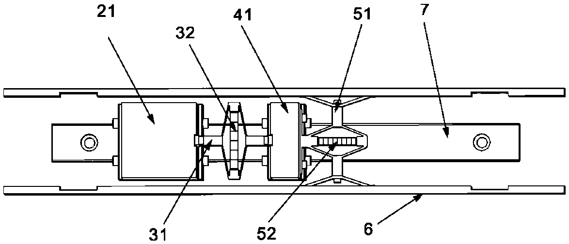
[0040] see figure 1 , an inertial impact motor with clamp control includes a flat base 8 , a pair of clamp guide rails 6 , linear slide rails 7 , a counterweight mechanism 2 , a quality mechanism 4 , a drive mechanism 3 and a clamp mechanism 5 .
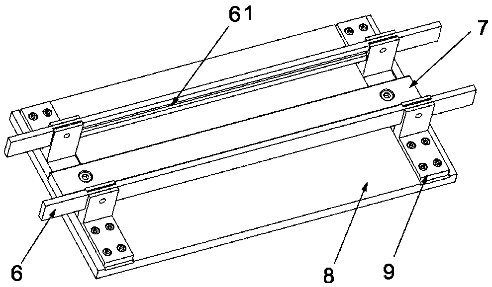
[0041] see image 3 The two ends of a pair of clamping guide rails 6 are respectively fixed on the base 8 through the support base 9, and the pair of clamping guide rails 6 are parallel to each other. Tight mechanism 1. Clamping rail grooves 61 are formed on the corresponding inner surfaces of the pair of clamping rails 6 .
[0042] see Figure 7 , the pretensioning mechanism 1 includes a double-ended stud 13, a pair of pretensioning springs 11, a pair of pretensioning clips 14, a pair of pretensioning springs 11 are respectively set on the two ends of the double-ended stud 13, corresponding to the...
PUM
 Abstract
Description
Claims
Application Information
 - R&D
- Intellectual Property
- Life Sciences
- Materials
- Tech Scout
- Unparalleled Data Quality
- Higher Quality Content
- 60% Fewer Hallucinations
Browse by: Latest US Patents, China's latest patents, Technical Efficacy Thesaurus, Application Domain, Technology Topic, Popular Technical Reports.
© 2025 PatSnap. All rights reserved.Legal|Privacy policy|Modern Slavery Act Transparency Statement|Sitemap|About US| Contact US: help@patsnap.com