Artificial ankle joint tibia component

A tibial and joint technology, applied in the field of artificial ankle tibial elements, can solve problems such as increased burden on patients, limited range of joint motion, and decreased function of artificial joints, and achieve the goals of reducing pain and burden, shortening recovery time, and shortening operation time Effect

Active Publication Date: 2020-04-21
科润泰克株式会社 +2
View PDF14 Cites 1 Cited by
  • Summary
  • Abstract
  • Description
  • Claims
  • Application Information

AI Technical Summary

Problems solved by technology

Especially in the recent research results, it is pointed out that heterotopic ossification presents obvious symptoms in about 5% of patients with the disease and thus leads to the problem of limited range of motion of the joints. In addition, it can cause artificial pain due to severe joint pain Significant decline in joint function
In order to solve the above-mentioned problems, a surgical intervention method of surgically removing the hypertrophic bone is required, which in turn leads to an increase in the burden on the patient due to reoperation

Method used


Image

  • Artificial ankle joint tibia component
  • Artificial ankle joint tibia component
  • Artificial ankle joint tibia component

Examples


Embodiment Construction

[0083] Next, the tibial element of the artificial ankle joint to which the present invention is applied will be described in detail with reference to the drawings. It should be noted that the same components are shown in figures with the same symbols as much as possible in all the drawings. Also, detailed descriptions of well-known functions and configurations that may obscure the gist of the present invention will be omitted. Unless otherwise clearly defined, the meanings of all terms used in this specification are the same as the general meanings of the corresponding terms understood by those skilled in the art to which the present invention belongs. When used in this specification In case of conflict of meanings of terms, the definitions used in this specification will control.

[0084] Next, the tibial element of the artificial ankle joint to which the present invention is applied will be described in detail with reference to the drawings.

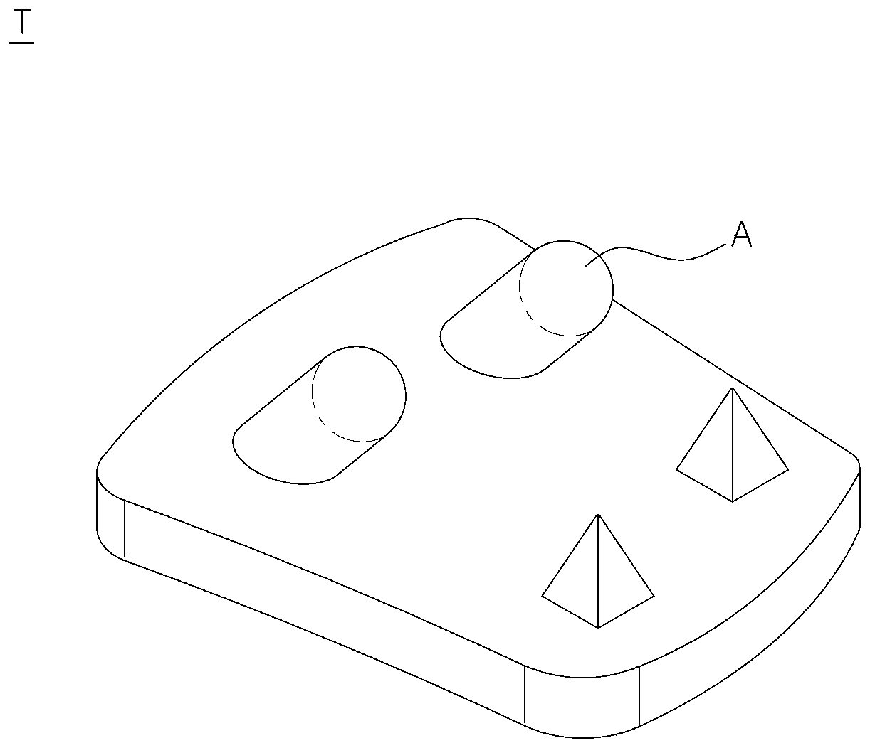
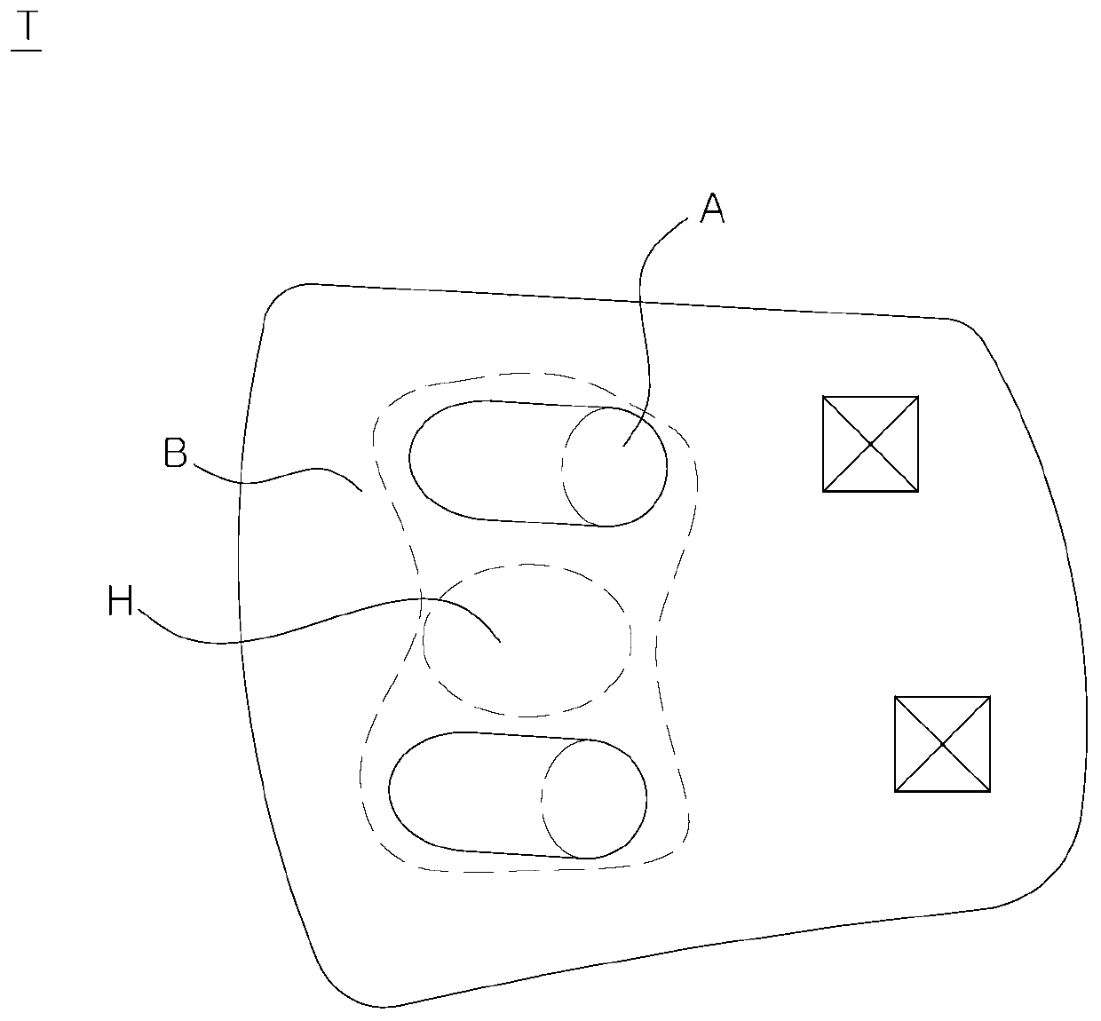
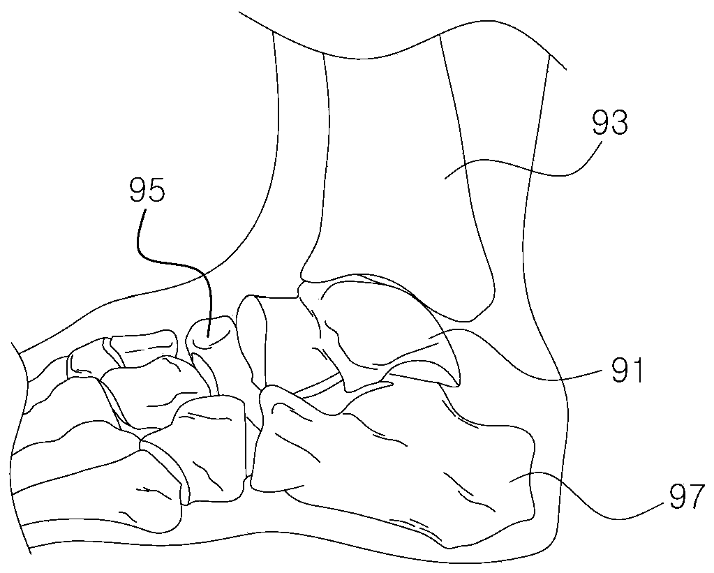
[0085] figure 1 is an obliqu...


PUM


Abstract

The present invention relates to an artificial ankle joint tibia component and, more specifically, to an implant being implanted in vivo. The implant comprises: a body part having a contact surface, which comes into contact with the cross section of the distal tibial joint, and a joint surface which faces the joint; and a fixing part extending at a fixed length upwardly from the contact surface. The fixing part comprises a blade which extends in a lateral direction and is formed in a single piece extending at a fixed length upwardly from the front-center of the contact surface. The blade comprises at least one rear blade unfolding at a predetermined angle with respect to the A-P line. Therefore, the present invention prevents stress concentration on one lateral blade and thus prevents breaks, enables extension of the contact surface area between the bone and the implant and thus enhances fixing force, and prevents marginal bone resorption by means of preventing rotation and distributing stress.

Description

technical field [0001] The present invention relates to an artificial ankle tibial element, in particular to an artificial ankle tibial element. The contact surface where the cutting surfaces of the articular surfaces meet and the articular surface facing the joint; and the fixed part is formed by extending a certain length from the upper side of the above-mentioned contact surface; wherein, the above-mentioned fixed part is extended from the front middle of the above-mentioned contact surface to the upper side Consisting of a single body formed at a certain length and including wings extended to one side, the wings include at least one rear wing spread out at a certain angle based on the front-to-back (AP) line, thereby preventing stress from concentrating on the side wing. It prevents it from breaking, strengthens the fixation force and prevents it from rotating by expanding the contact area between the bone and the implant, and prevents bone resorption around the wing by di...

Claims


Application Information

Patent Timeline
Patent Type & Authority Applications(China)
IPC IPC(8): A61F2/42
CPCA61F2/42A61F2/4202A61F2/30771A61F2002/4205A61F2002/30884A61F2002/30878A61F2002/30892A61F2002/30841A61F2002/30843
Inventor 李根培慎太珍
Owner 科润泰克株式会社
Why Eureka
Try Eureka