Eureka AIR delivers breakthrough ideas for toughest innovation challenges, trusted by R&D personnel around the world.

Garbage compression device for garbage salvage ship

A technology for garbage compression and salvage ships, which is used in presses, transportation and packaging, special-purpose ships, etc., can solve the problems of fragile devices, poor compression effect, and low compression efficiency, and achieves convenient subsequent crushing and continuous work. , The effect of preventing adhesion of garbage

Inactive Publication Date: 2020-04-24
LIXIN COUNTY YURUO INFORMATION TECH CO LTD
View PDF6 Cites 5 Cited by
  • Summary
  • Abstract
  • Description
  • Claims
  • Application Information

AI Technical Summary

Problems solved by technology

[0004] The object of the present invention is to provide a kind of rubbish compression device for a garbage salvage ship, to solve the problem that the existing garbage compression device mentioned in the above background technology does not remove the iron in the garbage when cleaning the garbage salvaged by the salvage ship. The high-quality garbage is separated, which makes it inconvenient to operate and easy to damage the device in the subsequent crushing and compression, and the existing garbage is not pretreated when it is crushed, so that the crushing efficiency is not high, resulting in a large garbage volume , the compression effect is not good, and the existing compression device has a simple structure and cannot perform continuous work, resulting in the problem of low compression efficiency

Method used


Image

  • Garbage compression device for garbage salvage ship
  • Garbage compression device for garbage salvage ship
  • Garbage compression device for garbage salvage ship

Examples


Embodiment Construction

[0025] The following will clearly and completely describe the technical solutions in the embodiments of the present invention with reference to the drawings in the embodiments of the present invention.

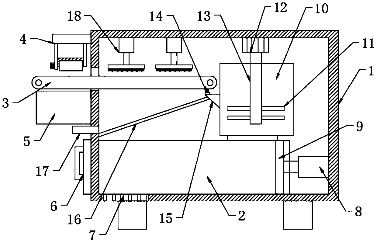
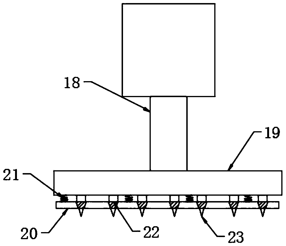
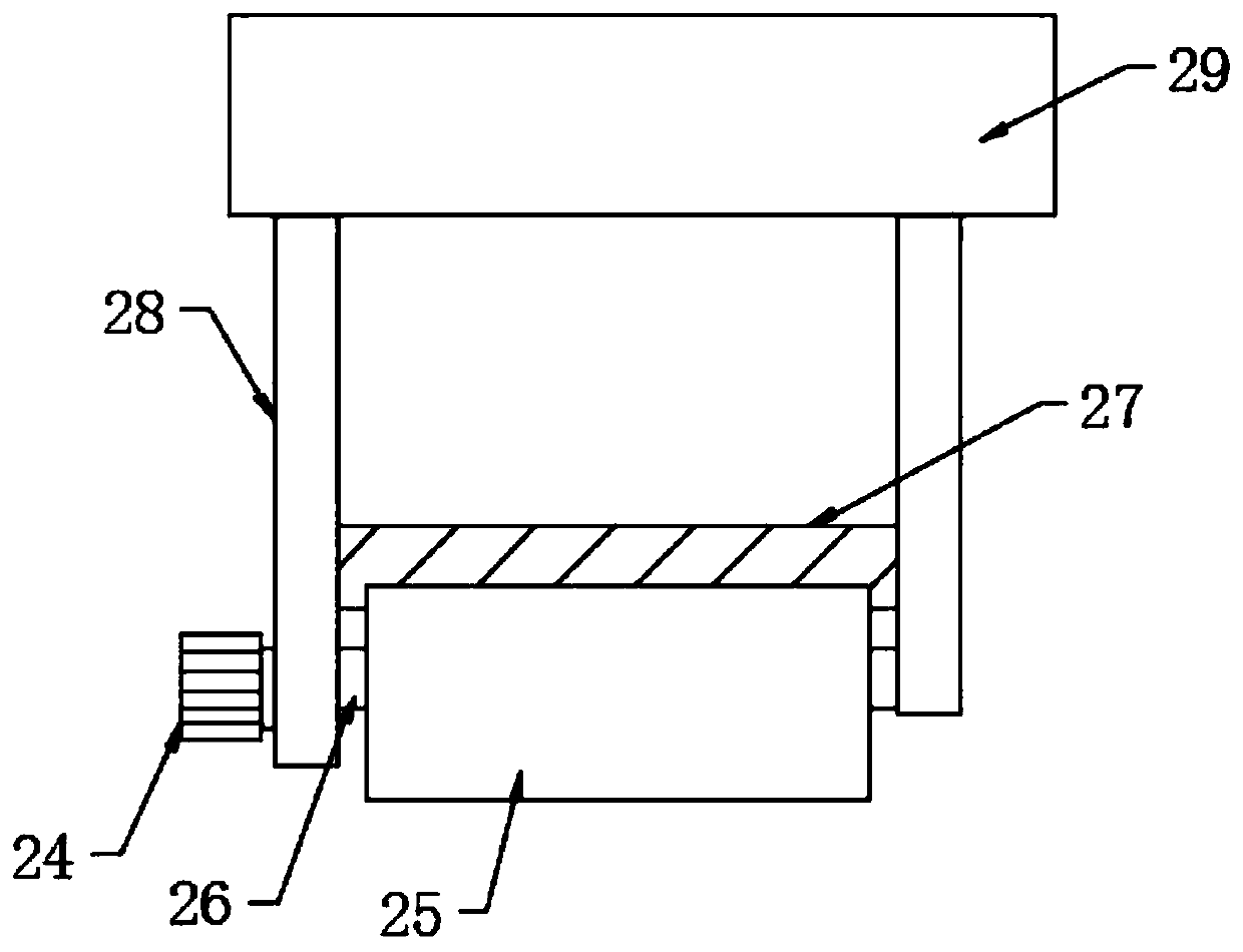
[0026] Such as Figure 1-4 As shown, the present invention provides a technical solution: a garbage compression device for salvage ships, including a treatment box 1, a conveying mechanism 3, an iron-absorbing mechanism 4, a crushing mechanism, a crushing mechanism and a compression mechanism, and the conveying mechanism 3 is located at One side of the outside of the treatment box 1, and one end of the conveying mechanism 3 extends inside the treatment box 1, the iron-absorbing mechanism 4 is located on the outside side of the treatment box 1, and the iron-absorbing mechanism 4 is located above the conveying mechanism 3, and the crushing mechanism is located The top inside of the processing box 1, and the crushing mechanism is located directly above the conveying mechanism 3, ...


PUM


Abstract

The invention discloses a garbage compression device for a garbage salvage ship. The device comprises a treatment box, a conveying mechanism, an iron attracting mechanism, a crushing mechanism, a smashing mechanism and a compressing mechanism. The conveying mechanism is located on one side of the outer portion of the treatment box. One end of the conveying mechanism extends to be located in the treatment box. The iron attracting mechanism is located on one side of the outer portion of the treatment box and located above the conveying mechanism. The crushing mechanism is located at the top endin the treatment box, and the crushing mechanism is located over the conveying mechanism. According to the invention, the conveying mechanism, the iron attracting mechanism, the crushing mechanism, the smashing mechanism and the compressing mechanism are arranged; salvaged garbage is conveyed by the conveying mechanism; iron garbage carried in the garbage is sucked out through the iron attractingmechanism while the garbage is conveyed, then the garbage on the conveying mechanism is preliminarily crushed through the crushing mechanism; the crushed garbage is conveyed into the smashing mechanism to be smashed; the smashed garbage is compressed by the compressing mechanism; and due to processized arrangement, continuous work can be conducted, and the compression efficiency is high.

Description

technical field [0001] The invention relates to the technical field related to garbage disposal, in particular to a garbage compression device for a garbage salvage ship. Background technique [0002] Garbage is solid waste generated in human daily life and production. Due to the large amount of discharge and complex and diverse components, it has a certain degree of pollution. With the increase in environmental protection this year, the cleaning of river waste has become more and more important. Now In some river courses, most of the garbage in the river is salvaged by salvage boats. Due to the large amount of garbage, in order to facilitate the transfer of garbage, it is necessary to compress the garbage. [0003] However, when the existing garbage compression device is cleaning the garbage salvaged by the salvage ship, because it does not separate the iron garbage in the garbage, it is inconvenient to operate and easy to damage the device in the subsequent crushing and co...

Claims


Application Information

Patent Timeline
Patent Type & Authority Applications(China)
IPC IPC(8): B09B3/00B09B5/00B03C1/18B02C1/12B02C18/10B30B9/06B63B35/32
CPCB02C1/005B02C1/12B02C18/0092B02C18/10B02C2201/06B03C1/18B09B3/00B09B5/00B30B9/06B63B35/32
Inventor 张若玉刘杰
Owner LIXIN COUNTY YURUO INFORMATION TECH CO LTD
Why Eureka
Eureka Blog
Learn More