Dehumidifier with multifunctional drainage function and drainage method

A dehumidifier, multi-functional technology, applied in heating methods, household appliances, mechanical equipment, etc., can solve the problems of water pump or other electrical parts damage, inconvenient parts replacement, single drainage function, etc., to prolong the service life and facilitate cleaning , Improve the effect of safety performance

Pending Publication Date: 2020-04-24
广东百奥电气有限公司
View PDF8 Cites 7 Cited by
  • Summary
  • Abstract
  • Description
  • Claims
  • Application Information

AI Technical Summary

Problems solved by technology

At present, the existing dehumidifier drainage methods include manual drainage, natural drainage and water pump drainage, but usually only one of these three drainage methods is set in the same dehumidifier, and the drainage function is relatively single. For a variety of complex workplaces, a single drainage function is not suitable, such as: dehumidifier drainage in laboratories and chemical factories. In the face of this situation, manual drainage or natural drainage water tanks are not compatible with the efficient work of the factory workshop. The purpose is contrary to the purpose; even some workshops produce corrosive domestic wastewater, which requires special drainage treatment. Obviously, manual drainage may harm the human body; further research has found that the water tank structure, water pump and electrical components in the existing market All placed in the water tank, it is inconvenient to replace the parts and the condensed water polluted by the workshop for a long time may cause damage to the water pump or other electrical parts

Method used


Image

  • Dehumidifier with multifunctional drainage function and drainage method
  • Dehumidifier with multifunctional drainage function and drainage method
  • Dehumidifier with multifunctional drainage function and drainage method

Examples


Embodiment Construction

[0035] The present invention provides a dehumidifier with multi-functional drainage and a drainage method. In order to make the purpose, technical solution and effect of the present invention clearer and clearer, the present invention will be further described in detail below with reference to the accompanying drawings and examples. It should be understood that the specific embodiments described here are only used to explain the present invention, not to limit the present invention.

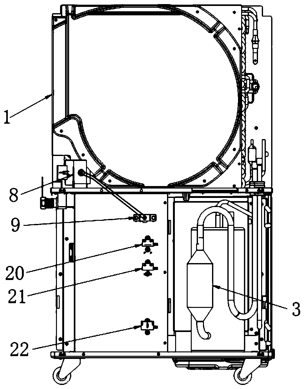
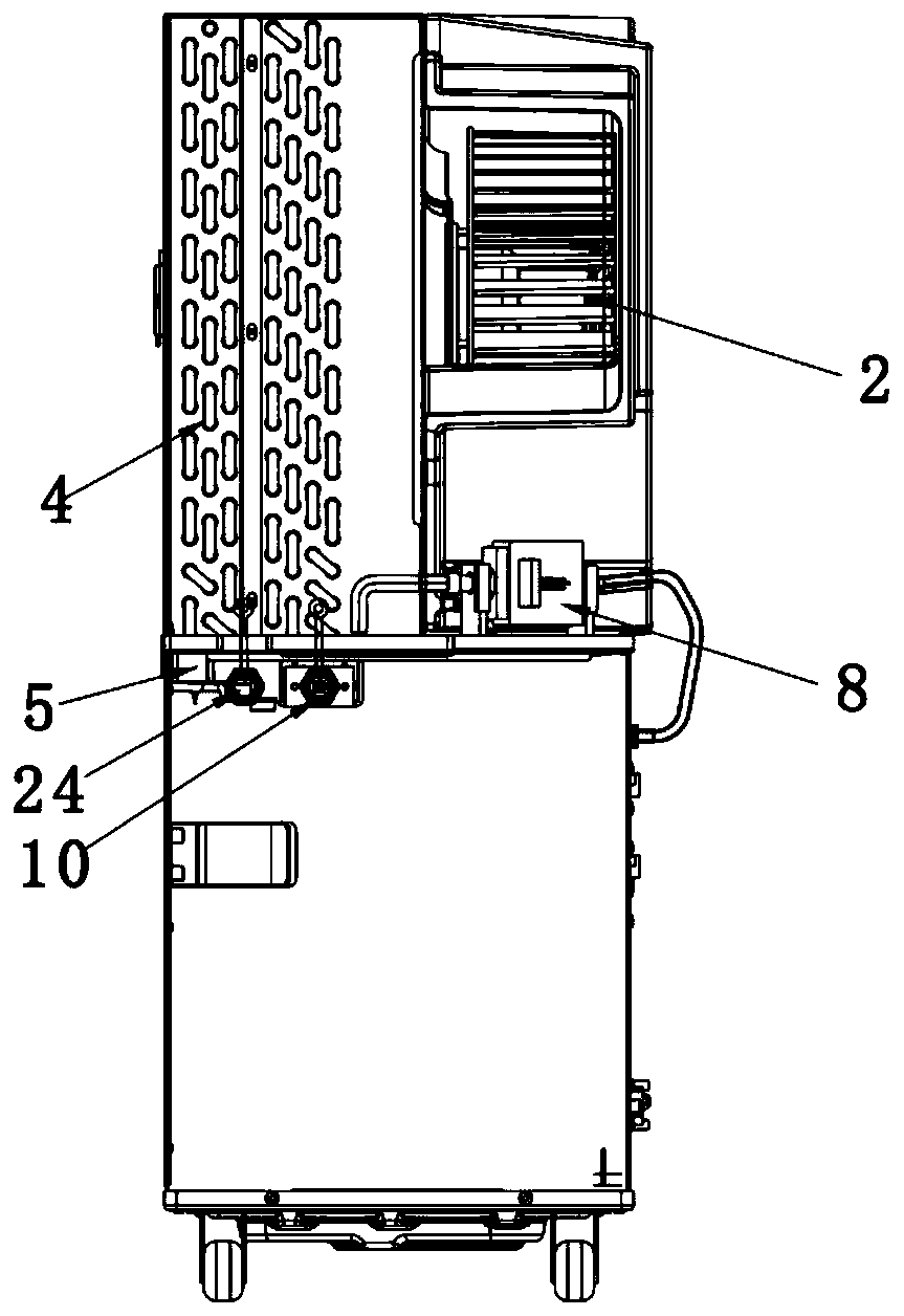
[0036] see figure 1 , figure 2 , Image 6 , the present invention provides a dehumidifier with multi-functional drainage, the dehumidifier includes a box body 1, and a dehumidification device, a drainage device and an electric control box assembly arranged in the box body, the dehumidification device includes a fan 2, a compressor 3. Two devices 4, the drainage device includes a water receiving tray 5 and a water tank 6, the electric control box assembly includes a control panel and a controll...


PUM


Abstract

The invention discloses a dehumidifier with a multifunctional drainage function and a drainage method. The dehumidifier comprises a box body and a drainage device, wherein the drainage device comprises a water receiving tray and a water tank, a first drainage opening of the water receiving tray directly face a water inlet of the water tank, the dehumidifier further comprises a water pump, a firstconnecting piece and a second connecting piece, the water pump is arranged in the middle of the box body, the first connecting piece and the second connecting piece are arranged on the box body, a water inlet of the water pump is connected with the first connecting piece through a pipeline, a water outlet of the water pump is connected with the second connecting piece, the water tank is provided with a drainage pipe, one end of the drainage pipe extends into the bottom of the water tank, the other end of the drainage pipe is connected with a third connecting piece arranged on the water tank, the third connecting piece is in tight butt joint with the first connecting piece, and a dehumidification device and the water pump are electrically connected with an electric cabinet assembly. According to the dehumidifier and the method, the dehumidifier separates the water pump from the water tank, the water pump is prevented from being eroded by water or acid and alkali, the service life of thewater pump is prolonged, the drainage method comprises an automatic drainage mode, a manual drainage mode and a direct drainage mode, and good applicability is achieved.

Description

technical field [0001] The invention relates to the technical field of dehumidifiers, in particular to a dehumidifier with multifunctional drainage and a drainage method thereof. Background technique [0002] With the rapid development of the modern economy and the continuous improvement of people's living standards, dehumidifiers are playing an increasingly important role in our lives. more and more. At present, the existing dehumidifier drainage methods include manual drainage, natural drainage and water pump drainage, but usually only one of these three drainage methods is set in the same dehumidifier, and the drainage function is relatively single. For a variety of complex workplaces, a single drainage function is not suitable, such as: dehumidifier drainage in laboratories and chemical factories. In the face of this situation, manual drainage or natural drainage water tanks are not compatible with the efficient work of the factory workshop. The purpose is contrary to ...

Claims


Application Information

Patent Timeline
Patent Type & Authority Applications(China)
IPC IPC(8): F24F3/14F24F13/20F24F11/89F24F13/22F24F11/30
CPCF24F3/14F24F13/20F24F11/89F24F13/22F24F11/30F24F2003/144
Inventor 罗家豪侯恩旭邓云常
Owner 广东百奥电气有限公司
Why Eureka
Try Eureka