Air cooler with air conditioning system

A technology for air conditioning systems and air coolers, applied in water shower coolers, heat exchanger types, direct contact heat exchangers, etc. The problem of dirt and other problems is eliminated, and the effect of convenient installation and use, effective temperature difference increase and compact system structure is achieved.

Inactive Publication Date: 2020-04-24
王丰海
View PDF0 Cites 0 Cited by
  • Summary
  • Abstract
  • Description
  • Claims
  • Application Information

AI Technical Summary

Problems solved by technology

[0004] In the process of realizing the present invention, the inventor found that the prior art has at least the following disadvantages: at present, the use effect of the traditional air cooler in summer is not ideal, and the air cooler takes away heat by the temperature rise of the air. If the ambient temperature is high, the air cooler The effective temperature difference will become smaller, and the heat exchange capacity of the air-cooled equipment will be insufficient, resulting in that the temperature of the medium in the heat exchanger cannot reach the specified temperature. To reach the specified temperature, the heat exchange area of ​​the air cooler needs to be increased on the one hand, but simply increasing the heat exchange area is often The problem cannot be completely solved, due to the limitation of the ambient temperature and the outlet temperature of the cooled medium
In actual operation, there is usually dirt on the outside of the fins, resulting in the cooling capacity of the air cooler in summer not reaching 70% of the rated heat dissipation. The user generally uses the method of spraying water or spray on the surface of the fins to compensate for the heat transfer of the air cooler The capacity is insufficient, but this will cause a serious waste of water resources. The spray water will spray water around under the suction of the fan, resulting in waste of spray water and rusting of the surrounding equipment. What is more serious is that after a period of operation, it will cause Severe fouling on the surface of finned tubes affects the subsequent use of the air cooler

Method used


Image

  • Air cooler with air conditioning system
  • Air cooler with air conditioning system

Examples


Embodiment Construction

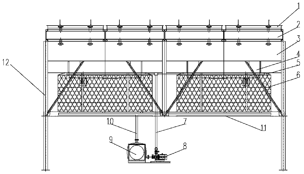
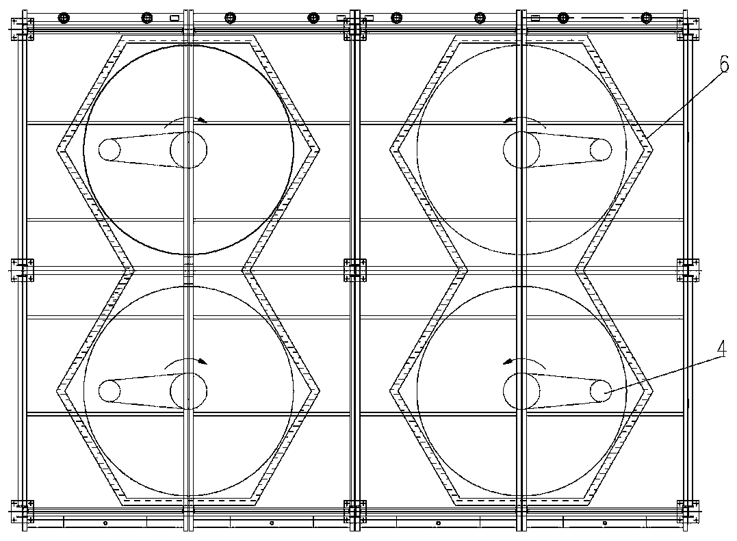
[0019] Examples, as attached figure 1 , figure 2 As shown, an air cooler with an air conditioning system includes an air cooler frame 12, and the air cooler frame 12 is provided with an air conditioning system, a fan shroud 5, a blower 4, an air chamber 3, a finned tube bundle 2, and an air cooler blinds1.

[0020] The air conditioning system includes a wet curtain 6, a water pump 8, a water tank 9, a water supply pipeline 7, and a water return pipeline 10.

[0021] The wet curtain 6 is arranged on the lower part of the air cooler frame 12, and the bottom of the wet curtain 6 is provided with a windshield 11, and the windshield 11 is used to prevent the bottom air from directly entering the blower 4 without passing through the wet curtain 6; On the upper side of the wind plate 11, one end of the return pipe 10 communicates with the bottom of the wet curtain 6, and the other end of the return pipe 10 communicates with the water tank 9, and the water tank 9 communicates with ...


PUM


Abstract

The invention discloses an air cooler with an air conditioning system. The air cooler comprises an air cooler framework. The air conditioning system, fan flow guide covers, air blowers, an air chamber, a fin pipe bundle and an air cooler louver are arranged on the air cooler framework. The air conditioning system comprises wet curtains, a water pump, a water tank, a water supply pipeline and a water return pipeline. The air blowers are arranged above the wet curtains. The fan flow guide covers are arranged between the air blowers and the wet curtains. The air cooler louver is arranged at the top of the air cooler framework. The fin pipe bundle is arranged on the lower portion of the air cooler louver. The air chamber is arranged between the fin pipe bundle and the air blowers. The air conditioning system is additionally mounted on a traditional dry air cooler and is used for achieving temperature reduction and humidity increase on environment air, the effective temperature difference of the heat exchanger is increased, the enthalpy value of air is increased, more heat is taken away when air is blown by a fan to pass through the fin pipe bundle, and the cooling temperature of cooledmedia in the heat exchanger is lower so as to meet production requirements.

Description

technical field [0001] The invention relates to heat exchange equipment used for condensation and cooling in petrochemical and oil and gas processing production, in particular to an air cooler with an air conditioning system. Background technique [0002] Ordinary air-cooled heat exchangers use ambient air as the cooling medium and sweep the outside of the finned tubes to cool or condense the high-temperature process fluid in the tubes. There are many names, such as finned fan heat exchangers, air-cooled Finned heat exchangers, finned tube air-cooled heat exchangers, etc., also known as air coolers or air heat exchangers, are collectively referred to as air coolers. [0003] With the development of industry, especially the development of oil refining, petrochemical, metallurgy and electric power industries, water consumption has increased sharply, and many areas have experienced water shortages in large areas. People are paying more and more attention to protecting the envi...

Claims


Application Information

Patent Timeline
Patent Type & Authority Applications(China)
IPC IPC(8): F28C1/14F28F25/08F28F25/02F28F25/06
CPCF28C1/14F28F25/02F28F25/06F28F25/08
Inventor 王丰海韩港港
Owner 王丰海
Why Eureka
Try Eureka