Rotational inertia test method

A technology of moment of inertia and test method, applied in the field of measurement, can solve problems such as large difference between calculation results and actual values, out-of-tolerance non-processing dimensions, and complex installation structure, achieving high measurement efficiency and measurement accuracy, low friction resistance, The effect of high transmission efficiency

Active Publication Date: 2020-04-24
重庆市綦齿齿轮研究院有限公司
View PDF9 Cites 0 Cited by
  • Summary
  • Abstract
  • Description
  • Claims
  • Application Information

AI Technical Summary

Problems solved by technology

[0002] The moment of inertia of the rotating parts of the transmission has a great influence on the performance of the synchronizer. The existing method is mainly calculated by three-dimensional software. Due to the large number of parts and complex structure, and the non-processing dimensions in the manufacturing process of the parts are out of tolerance, the calculation results are different from the actual ones. large value difference
However, it is not feasible to measure the moment of inertia of each part separately due to factors such as large quantity and complex installation structure.

Method used


Image

  • Rotational inertia test method
  • Rotational inertia test method

Examples


Embodiment 1

[0041] The formula for calculating the moment of inertia is Wherein, Jx is moment of inertia, and the application is simplified to J; This application is simplified to K; ∑m z (F e ) is the resultant torque, which is simplified as M in this application.

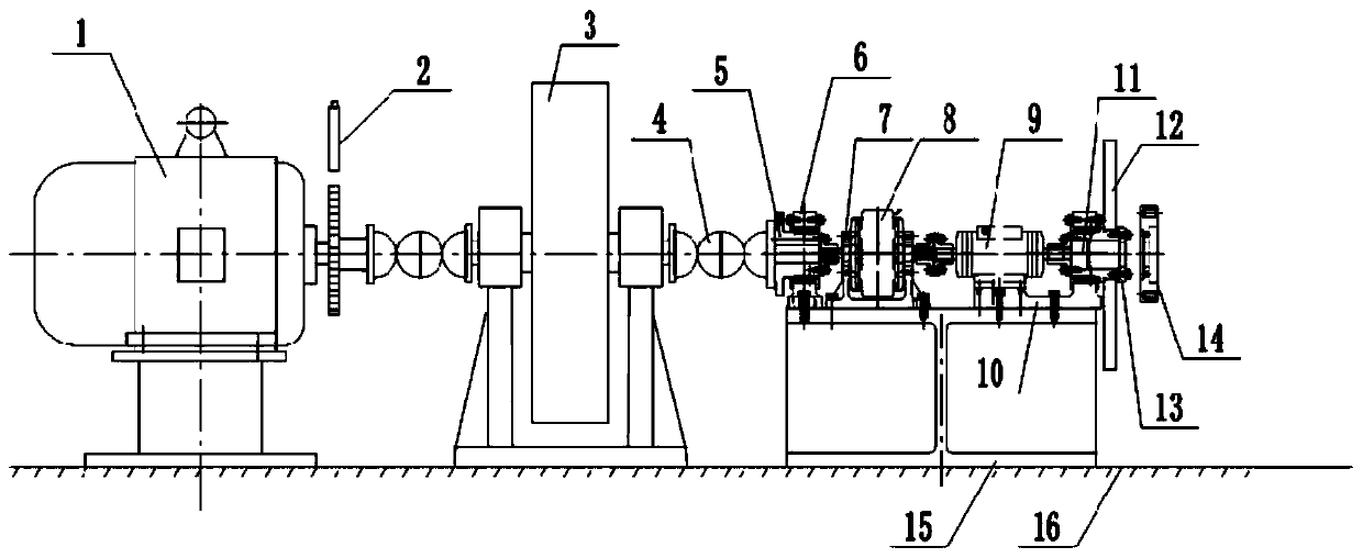
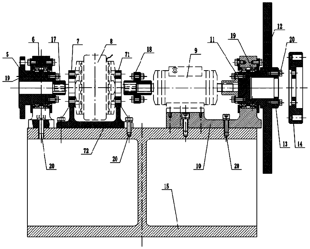
[0042] A method for testing moment of inertia, comprising the steps of:

[0043] Step 1: Determine the range of inertia: Calculate the equivalent moment of inertia of several commonly used assemblies to be measured to obtain a range of inertia.

[0044] Step 2: Design the standard inertia disk 12: take the maximum value, the minimum value and several point values ​​in the middle of the inertia range, and design and manufacture the torus-shaped standard inertia disk 12 according to these inertia values; the standard inertia disk 12 Determination of the value According to the theoretical value or estimated value of the tested assembly, design and manufacture standard inertial discs 12 at equal intervals of 50% to 200% of ...

Embodiment 2

[0063] The difference between this embodiment and Embodiment 1 is that in step 5, if the inertia of the measured assembly is small, an appropriate standard inertia disk can be selected as an additional disk of the measured assembly for amplified measurement, and the total The moment of inertia of the measured assembly can be obtained by subtracting the moment of inertia of the standard inertia disk as an additional disk from the moment of inertia.

[0064] In the actual production design, the inertia value of the tested assembly is relatively large, and of course it is relatively small. If the estimated inertia value of the tested assembly is relatively large, remove the standard inertia plate and directly place the measured The assembly can be installed on the moment of inertia measuring device for measurement; if the estimated inertia value of the measured assembly is small, it can be measured by zoom-in measurement, so that the measured data can be more accurate. With such ...


PUM


Abstract

The invention relates to the technical field of measurement, and discloses a rotational inertia test method which comprises the following steps: step 1, determining an inertia range; step 2, designinga standard inertia disc; step 3, testing and acquiring the acceleration value of the standard inertia disc under a constant torque; step 4, fitting a smooth continuous curve; step 5, testing the tested assembly; and step 6, calculating the actual inertia value. The equivalent moment of inertia of the measured assembly with a complex structure can be directly measured, the method is convenient tomeasure and high in result accuracy, the obtained inertia value can be directly used for design and calculation of parts associated with the measured assembly without measuring all the parts of the measured assembly one by one like the existing method, and thus the measurement efficiency and the measurement accuracy are higher.

Description

technical field [0001] The invention belongs to the technical field of measurement. Background technique [0002] The moment of inertia of the rotating parts of the transmission has a great influence on the performance of the synchronizer. The existing method is mainly calculated by three-dimensional software. Due to the large number of parts and complex structure, and the non-processing dimensions of the parts are out of tolerance in the manufacturing process, the calculation results are different from the actual ones. The values ​​vary greatly. However, it is not feasible to measure the moment of inertia of each part separately due to factors such as large quantity and complex installation structure. Therefore, it is necessary to design a method to directly measure the moment of inertia of complex structures. Contents of the invention [0003] The purpose of the present invention is to provide a test method that can directly measure the moment of inertia of complex str...

Claims


Application Information

Patent Timeline
Patent Type & Authority Applications(China)
IPC IPC(8): G01M1/10
CPCG01M1/10
Inventor 陈胜
Owner 重庆市綦齿齿轮研究院有限公司
Why Eureka
Try Eureka