Guide rail type ship shore power charging device

A charging device and rail-type technology, which is applied to battery circuit devices, circuit devices, collectors, etc., can solve the problems of increasing the work intensity of operators, slow interface installation speed, affecting the movement of personnel and vehicles, etc., to solve the problem of potential safety hazards And aesthetic problems, improve the degree of automation, improve the effect of charging efficiency

Active Publication Date: 2020-04-24
ZHEJIANG TUNA ENVIRONMENTAL SCI & TECH
View PDF6 Cites 5 Cited by
  • Summary
  • Abstract
  • Description
  • Claims
  • Application Information

AI Technical Summary

Problems solved by technology

[0003] When the work starts and ends, the cable connector is separated from the power supply and stuffed into the storage box, resulting in slow installation of the interface and low efficiency. The equipment requires manual handling, installation and docking, the degree of automation is too low, and it takes up space on the ship.
When there are many ships in the port that need to be charged, the docking of the plug before charging and the pulling out of the plug after charging require a lot of manual operations. On the one hand, the work intensity of the operator is increased, and on the other hand, the utilization rate of the equipment is reduced.
In addition, the traditional shore power cables are directly hung on the ship or most of the cables are placed directly on the ground, which is very unsightly and will affect the movement of people and vehicles, posing safety hazards

Method used


Image

  • Guide rail type ship shore power charging device
  • Guide rail type ship shore power charging device
  • Guide rail type ship shore power charging device

Examples


Embodiment Construction

[0022] The present invention will be further described below in conjunction with accompanying drawing and specific embodiment:

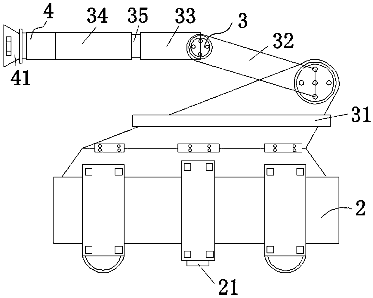
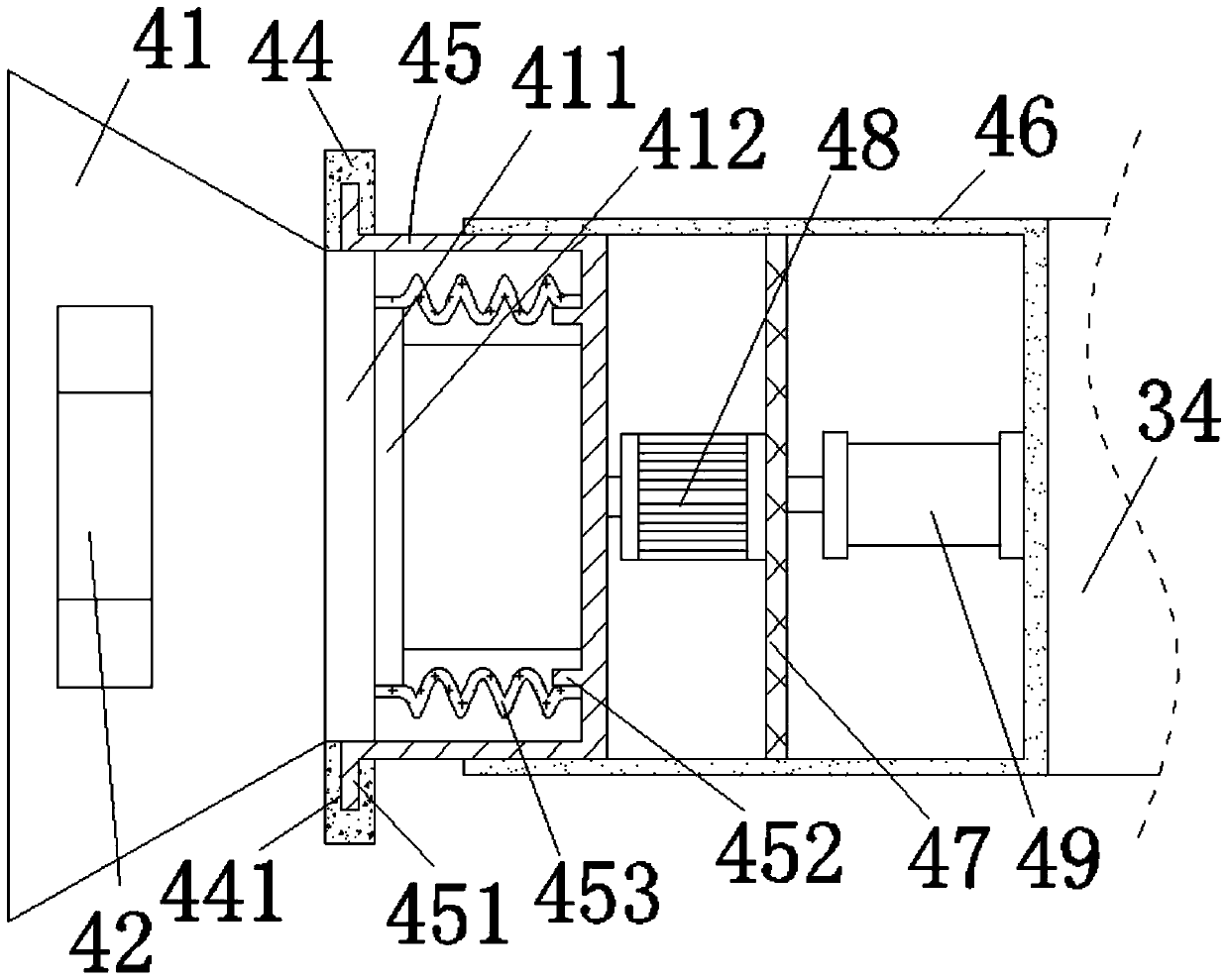
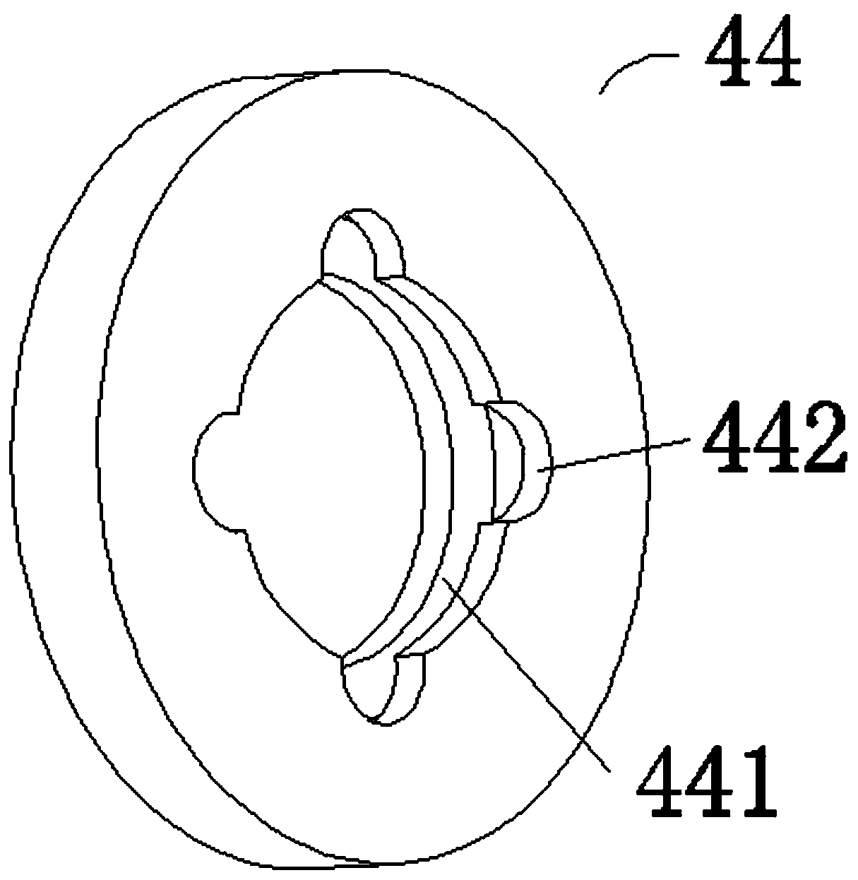
[0023] Such as Figure 1 to Figure 7 As shown, a guide rail type ship shore power charging device includes two parallel guide rails 1 and a vehicle 2 that can slide back and forth on the two guide rails 1, and a four-degree-of-freedom mechanical arm mechanism 3 is installed on the vehicle 2 The front end of the mechanical arm mechanism 3 is equipped with a charging structure 4, the charging structure 4 includes a plug 41, an infrared sensor 42 and an ultrasonic sensor 43 respectively installed on both sides of the front end of the plug 41 housing, fixed with the front end of the mechanical arm mechanism 3 The connected guide sleeve 46, the limit sleeve 45 that can be rotatably and slidably embedded in the annular inner wall of the guide sleeve 46, and the positioning sleeve 44 that is fixedly sleeved on the outer wall of the middle part of the plug 4...


PUM


Abstract

The invention discloses a guide rail type ship shore power charging device. The device comprises guide rails and a vehicle capable of sliding back and forth on the two guide rails, a mechanical arm mechanism is mounted on the vehicle, and a charging structure is mounted at the front end of the mechanical arm mechanism. The charging structure comprises a plug, an infrared sensor, an ultrasonic sensor, a guide sleeve, a limiting sleeve and a positioning sleeve. The limiting sleeve is connected with the plug through a hose. The positioning sleeve and the limiting sleeve realize rotary clamping connection or separation through the matching effect of a motor and an air cylinder. An embedded hole for a cable for supplying power to the charging structure to penetrate through is embedded between the two guide rails, a cable winch for winding and unwinding the cable is installed at the end point of one end of each guide rail, and limiting pieces for preventing the vehicle from rushing out of the guide rails are installed at the end points of the two ends of each guide rail respectively. Automatic butt joint of the charging plug and the charging interface on the ship is achieved, the automation degree of port operation is improved, and damage to the charging plug and the charging interface of the ship due to violent fluctuation of the water surface during charging is prevented.

Description

technical field [0001] The invention relates to the technical field of ship shore power, in particular to a guide rail type ship shore power charging device. Background technique [0002] At this stage, most of the ship shore power is to install the cable reel on the ship. Due to the limited installation space, a compact design is required to adapt to the installation space on the ship. The speed of retracting and unwinding the cable is a fixed value, the installation location of the reel is relatively fixed, and the pulling force of the cable needs to be detected in real time. Take it out and connect the power supply. [0003] When the work starts and ends, the cable connector is separated from the power supply and stuffed into the storage box, resulting in slow installation of the interface and low efficiency. The equipment requires manual handling, installation and docking, the degree of automation is too low, and it takes up space on the ship. . When there are many sh...

Claims


Application Information

Patent Timeline
Patent Type & Authority Applications(China)
IPC IPC(8): H02J7/00
CPCH02J7/0042Y02T90/14Y02T10/7072Y02T10/70
Inventor 金猛赵博诸正元朱建中范德华王亚辉王博婷沈柯华满中国宋超
Owner ZHEJIANG TUNA ENVIRONMENTAL SCI & TECH
Why Eureka
Try Eureka