
Direct-drive transmission powder concentrator with motor placed inside rotor

A powder separator and rotor technology, applied in the direction of solid separation, separation of solids from solids by air flow, chemical instruments and methods, etc., can solve the problem of large pressure difference between wind and material outlet, reduce the maintenance times of powder separator, reduce Fan operation power consumption and other issues, to achieve the effect of reducing local pressure difference, reducing equipment maintenance times, reducing fan power consumption

Pending Publication Date: 2020-04-28
中材(天津)粉体技术装备有限公司 +1
View PDF0 Cites 0 Cited by
  • Summary
  • Abstract
  • Description
  • Claims
  • Application Information

AI Technical Summary

Problems solved by technology

[0004] In order to solve the problems of frequent maintenance of the transmission shaft system, large pressure difference between the wind and the material outlet, and increased power consumption of the fan in the existing powder separator structure, the present invention proposes a direct drive powder separator with the motor placed inside the rotor. The powder classifier can greatly reduce the cost of equipment and process structure, increase the service life of the motor, reduce the maintenance times of the powder classifier, and reduce the power consumption of the fan operation

Method used


Image

  • Direct-drive transmission powder concentrator with motor placed inside rotor
  • Direct-drive transmission powder concentrator with motor placed inside rotor

Examples


Embodiment Construction

[0022] In order to further understand the invention content, characteristics and effects of the present invention, the following examples are given, and detailed descriptions are as follows in conjunction with the accompanying drawings:

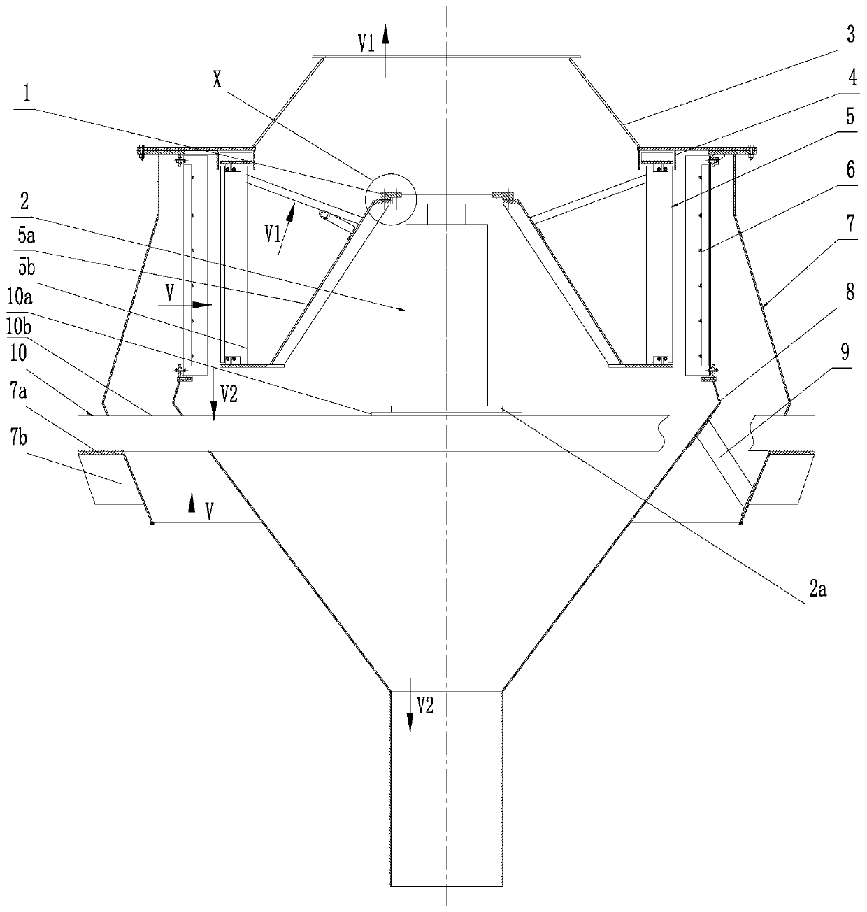
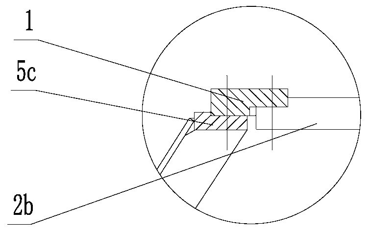
[0023] see figure 1 and 2 , a direct-drive powder separator with a motor placed inside the rotor, comprising an upper housing 3, a lower housing 7, a motor 2, a rotor 5, several wind guide vanes 6 and a feeding cone 8, and a lower housing 7 The upper shell 3 is fixed on the upper part, and the lower shell 7 is fixed on the middle shell of the vertical mill. The lower shell 7 fixes the blanking cone 8 through the support tube 9, and the air and At the material inlet, between the feeding cone 8 and the lower casing 7, a number of wind guide blades 6 are uniformly distributed in the circumferential direction, and are used to guide the wind and the material into the swirl area generated by the rotation of the rotor. Several wind guide vanes 6 a...


PUM


Abstract

The invention relates to a direct-drive transmission powder concentrator with a motor placed inside a rotor. The direct-drive transmission powder concentrator with the motor placed inside the rotor comprises an upper shell, a lower shell, the motor, the rotor, a plurality of air guiding blades and a discharging cone, wherein an air and material outlet is formed over the upper shell, obstacles do not exist from the rotor to the air and material outlet in the top, the motor is arranged in the rotor, an output shaft of the motor is connected with the rotor through a transmission assembly, the motor is fixed to the lower shell through a motor supporting frame, the motor supporting frame comprises a plurality of cross beams and a motor supporting plate, each cross beam is inserted from an opening in one side of the lower shell, penetrates through the discharging cone and then penetrates out of the other side of the lower shell, the motor supporting plate is fixed among the plurality of cross beams, and a motor bottom plate of the motor is fixed on the motor supporting plate. According to the direct-drive transmission powder concentrator, the equipment and process structure cost can be greatly reduced, the service life of the motor is prolonged, the maintenance frequency of the powder concentrator is reduced, the operation power consumption of a fan is reduced, and huge market spaceand popularization significance are achieved.

Description

technical field [0001] The invention belongs to the technical field of powder separators, in particular to a direct-drive powder separator with a motor placed inside a rotor. Background technique [0002] After years of development of material grinding and screening technology, the third-generation powder classifier has been widely used. It mainly uses the rotation of the rotor to generate swirling flow. When the wind carries the material through the swirling flow area, the material is screened with different particle sizes under the action of centrifugal force, wind traction force and gravity. The qualified particle size materials with small centrifugal force are brought to the outside of the powder separator under the traction of the wind, and collected by the dust collector; while the unqualified particle size materials with large centrifugal force are dropped again under their own gravity. Fall back into the millstone and grind again. At the same time, according to the...

Claims


Application Information

Patent Timeline
Patent Type & Authority Applications(China)
IPC IPC(8): B07B7/083B07B11/06B07B11/02B07B11/00
CPCB07B7/083B07B11/00B07B11/02B07B11/06
Inventor 竹永奎申占民赵剑波吕珂馨
Owner 中材(天津)粉体技术装备有限公司
Learn More