Pneumatic system of nail gun, pneumatic nail gun and nailing machine

A pneumatic system and nail gun technology, applied in nailing tools, manufacturing tools and other directions, can solve the problems of low nailing efficiency, increase artificial fatigue strength, and cannot use automatic nailing of plates, and achieve simple structure and easy promotion. and use, easy to operate effect

Pending Publication Date: 2020-04-28
MINGZHU FURNITURE CO LTD
View PDF1 Cites 0 Cited by
  • Summary
  • Abstract
  • Description
  • Claims
  • Application Information

AI Technical Summary

Problems solved by technology

[0012] Due to the above structure, every time the pneumatic nail gun works, it can only work by manually pressing the button. Therefore, the structure of the nail gun cannot be applied to automatic processing equipment to realize automatic nailing of plates. Manual nailing increases the artificial fatigue strength and the nailing efficiency is low

Method used


Image

  • Pneumatic system of nail gun, pneumatic nail gun and nailing machine
  • Pneumatic system of nail gun, pneumatic nail gun and nailing machine
  • Pneumatic system of nail gun, pneumatic nail gun and nailing machine

Examples


Embodiment 1

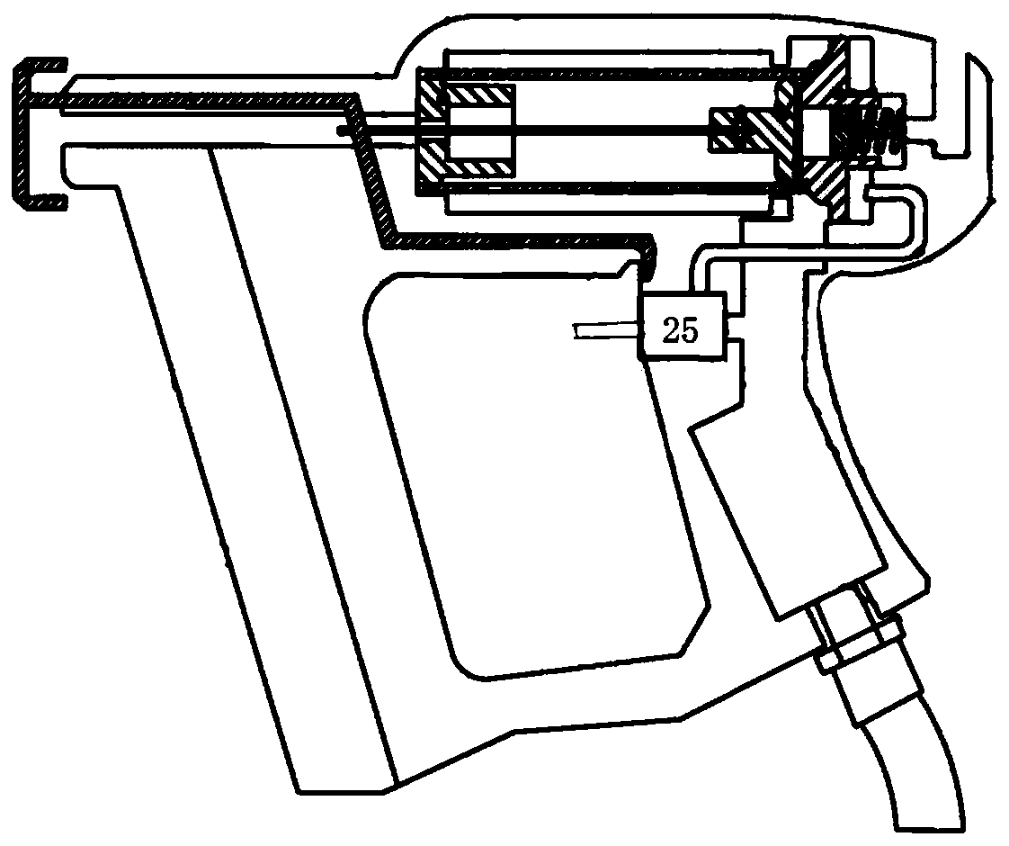
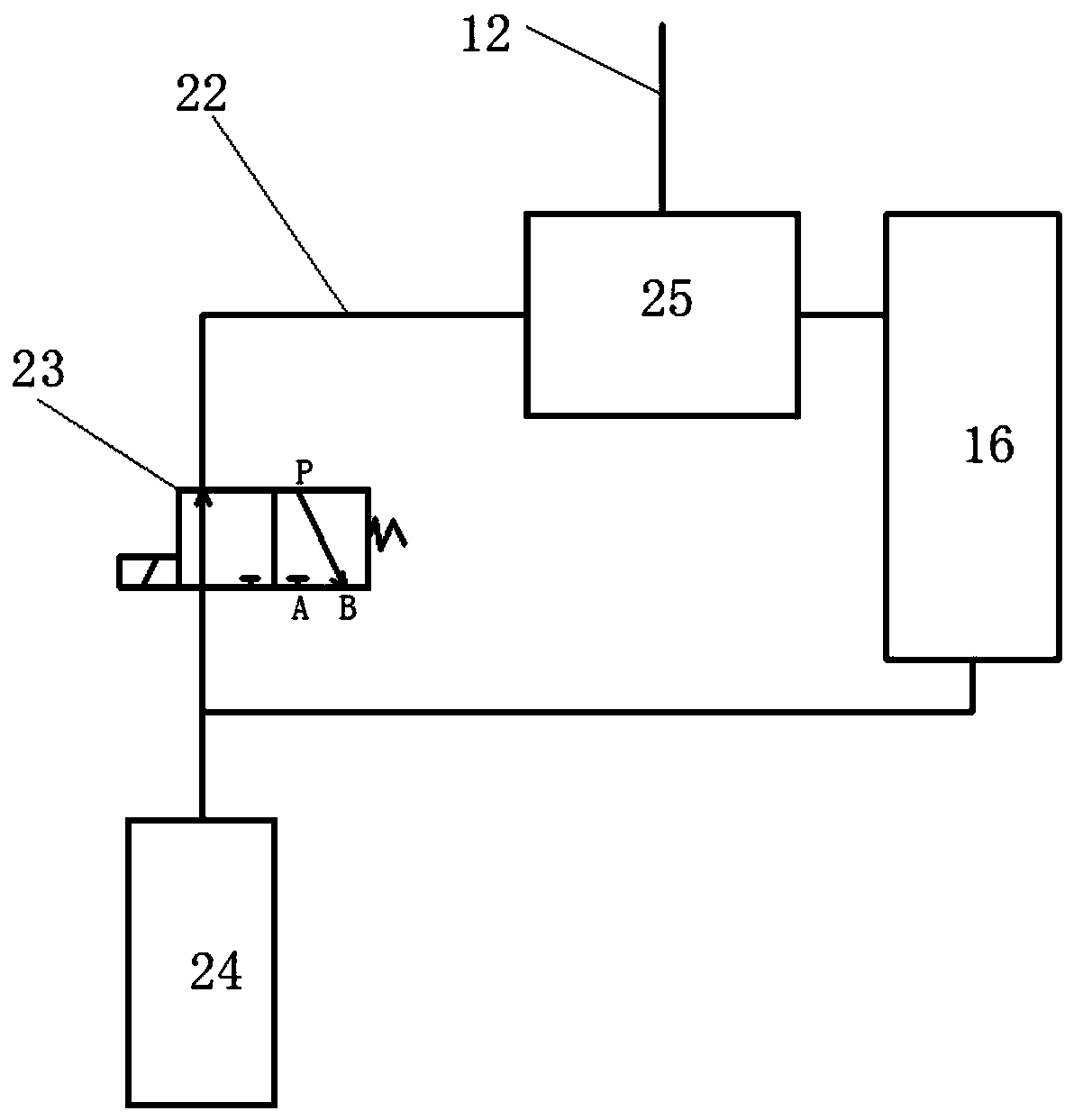
[0039] A pneumatic system of a nail gun, which includes a switching mechanism 25, an electromagnetic reversing valve 23, an air source 24 and a controller; The electromagnetic reversing valve 23 communicates with the air source 24; the air storage chamber 16 communicates with the air source 24; the electromagnetic reversing valve 23 is connected and controlled by the controller; The gas in the gas storage chamber 16 switches the communication state between the gas guide tube 12 and the gas storage chamber 16 .

[0040] The switching mechanism 25 includes a switching chamber 251, a switching piston 253 is arranged in the switching chamber 251, and a connecting seat 252 is inserted into the front end of the switching chamber 251; the connecting seat 252 is provided with a switching chamber air inlet channel 254, The front end of the switching chamber intake passage 254 is connected to the air source 24 through the switching chamber intake pipe 22, and the electromagnetic reversi...

Embodiment 2

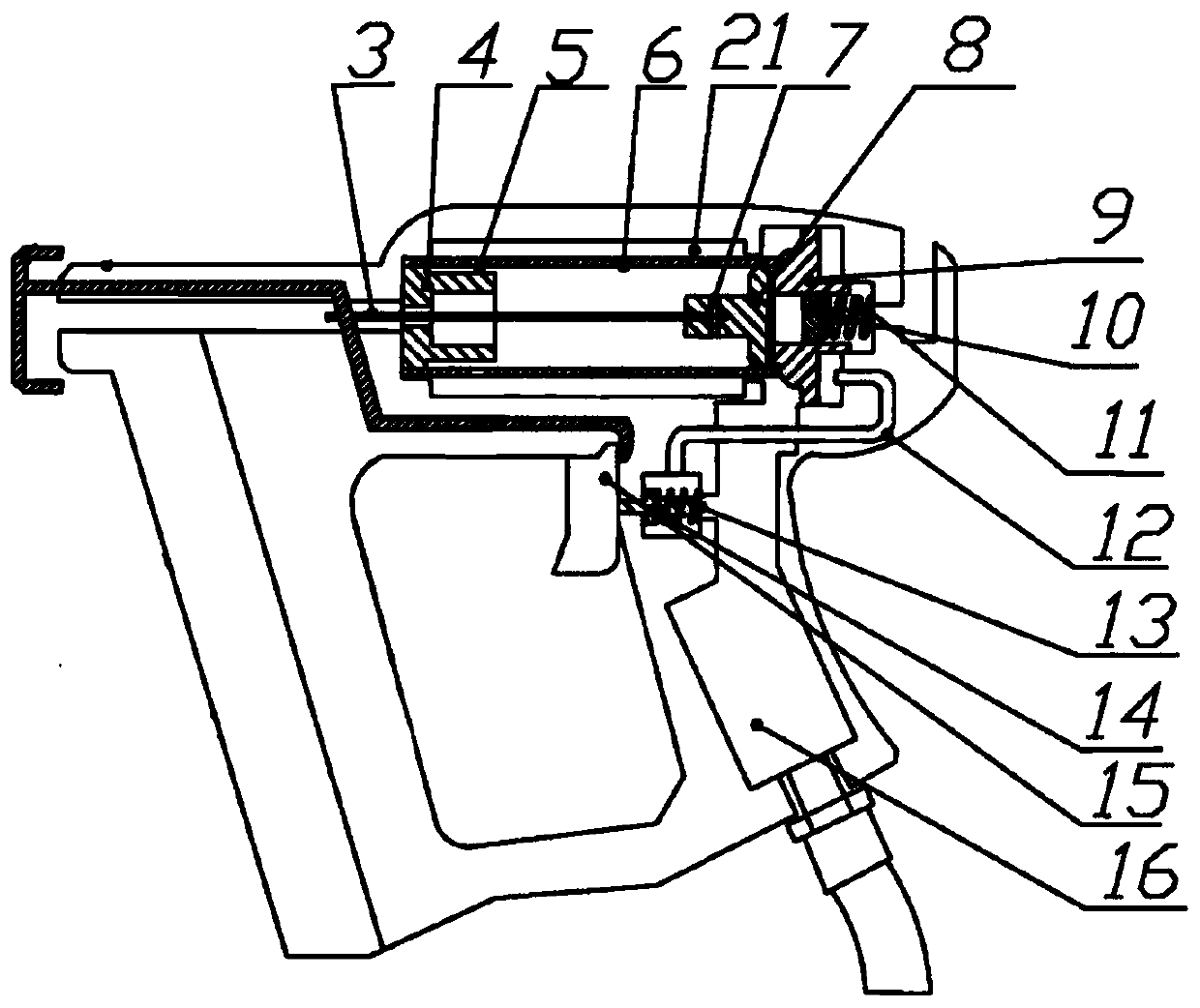
[0048] A pneumatic nail gun, which includes a gun body, a gun handle, a nail clip device, an air storage chamber 16, an air guide pipe 12, a piston 9, a firing pin rod 8, an air cylinder 6 and a firing pin 3, the gun handle is connected to the gun body, The gas storage chamber 16 is arranged inside the handle of the gun, the tail of the gas storage chamber 16 is connected to the gas source 24, the gas storage chamber 16 leads to the top of the piston 9, and a closed space is formed between the bottom of the piston 9 and the bottom of the inner wall of the gun body. It communicates with the closed space, the top of the piston 9 is connected to the bottom of the gas cylinder 6, the top of the gas cylinder 6 is equipped with a gas cylinder plug 4, the outer wall of the gas cylinder 6 is provided with a gas cylinder hole 5, the center of the gas cylinder plug 4 is provided with a channel, and the striker rod 8 is installed inside the gas cylinder 6, The bottom of the firing pin rod...

Embodiment 3

[0057] An automatic nailing machine, which includes the pneumatic nail gun in Embodiment 2, the pneumatic nail gun is arranged on the body, and the body is used to drive the pneumatic nail gun forward, backward, left, right, up, Move down.


PUM


Abstract

The invention discloses a pneumatic system of a nail gun, a pneumatic nail gun and a nailing machine. The pneumatic system involves a switching mechanism, an electromagnetic reversing valve, a gas source and a controller, the switching mechanism communicates with a gas guide pipe and a gas storage chamber, and communicates with the gas source through the electromagnetic reversing valve; the gas storage chamber communicates with the gas source, and the electromagnetic reversing valve is connected with and controlled by the controller; and the switching mechanism is used for receiving gas from the gas source or the gas storage chamber and switching the communicating state between the gas guide pipe and the gas storage chamber. When the pneumatic system is applied to a nail gun structure, a nail gun can achieve automatic nailing; and meanwhile, the invention further designs the pneumatic nail gun and the nailing machine according to the pneumatic system.

Description

technical field [0001] The invention relates to furniture manufacturing equipment, in particular to a pneumatic system of a nail gun, a pneumatic nail gun and a nailing machine. Background technique [0002] The patent with the application number "CN201520747018.8" discloses a pneumatic nail gun structure, which includes a gun body, a gun handle, a nail clamp device and a pneumatic device. The afterbody of button 15 is embedded in the handle of the gun. [0003] The pneumatic device includes a button 15, an air storage chamber 16, an air guide pipe 12, a piston 9, a firing pin rod 8, an air cylinder 6 and a firing pin 3. The air storage chamber 16 is arranged inside the handle of the gun, and the tail of the air storage chamber 16 is provided with an air intake pipe for storing air. The chamber 16 leads to the top of the piston 9, a closed space is formed between the bottom of the piston 9 and the bottom of the inner wall of the gun body, the end of the air guide tube 12 co...

Claims


Application Information

Patent Timeline
Patent Type & Authority Applications(China)
IPC IPC(8): B25C1/04
CPCB25C1/041
Inventor 林永刚王建兵
Owner MINGZHU FURNITURE CO LTD
Why Eureka
Try Eureka