Multi-time mode-locking hydraulic oil path structure of injection molding machine and multi-time mode-locking method thereof

A hydraulic oil circuit and injection molding machine technology, which is applied in the field of hydraulic oil circuit structure, can solve problems such as warping, exhaust effect, and deformation of injection molds, etc., to prolong the life of spare parts, eliminate pressure shock, and improve mechanical properties. Effect

Pending Publication Date: 2020-04-28
BORCH MACHINERY
View PDF0 Cites 0 Cited by
  • Summary
  • Abstract
  • Description
  • Claims
  • Application Information

AI Technical Summary

Problems solved by technology

[0003] However, the traditional working method of injection molding machine has the following three disadvantages: 1) The process of compressing the hydraulic oil in the clamping cavity to generate the clamping force is divided into two stages. First, in the low pressure area, multiple pumps are involved in the work to quickly replenish the clamping cavity Second, in the high-pressure area, a large-displacement high-pressure pump is used to generate high-pressure mold clamping; however, due to the relatively large inertia of the large-displacement pump, the pressure cannot be boosted steadily at high pressure, and the pressure overshoot reaches more than 10 bar. It has a great influence on the life of the clamping mechanism; 2) During the...

Method used


Image

  • Multi-time mode-locking hydraulic oil path structure of injection molding machine and multi-time mode-locking method thereof
  • Multi-time mode-locking hydraulic oil path structure of injection molding machine and multi-time mode-locking method thereof
  • Multi-time mode-locking hydraulic oil path structure of injection molding machine and multi-time mode-locking method thereof

Examples


Embodiment Construction

[0034] Below, the present invention will be further described in conjunction with the accompanying drawings and specific implementation methods. It should be noted that, under the premise of not conflicting, the various embodiments described below or the technical features can be combined arbitrarily to form new embodiments. .

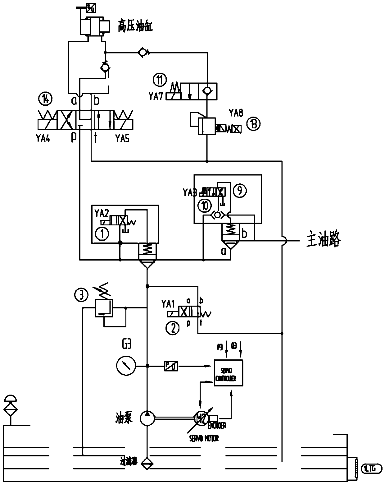
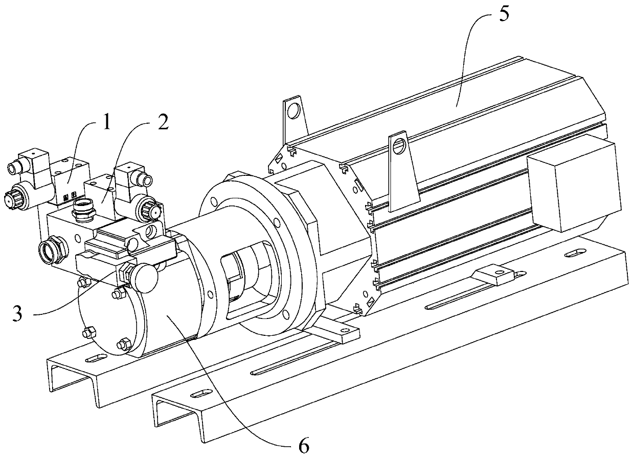
[0035] The multiple clamping hydraulic oil circuit structure of the injection molding machine of the present invention is as follows: Figure 1-Figure 5 As shown, it includes an oil tank for storing hydraulic oil, a first oil pump 6 for delivering hydraulic oil, an oil pump for the main oil circuit, a servo motor 5 for powering the oil pump, communicating with the oil pump and used to drive the mold opening and closing Clamping high-pressure cylinder;

[0036] The first control valve 1 used to control the on-off of the first oil pump 6 and the second control valve used to control the conduction of the hydraulic oil to the mold-clamping high-pressure c...


PUM


Abstract

The invention discloses a multi-time mode-locking hydraulic oil path structure of an injection molding machine. The structure comprises an oil tank, a first oil pump, a main oil path oil pump, a servomotor and a mode-locking high-pressure oil cylinder; a first control valve and a second control valve are arranged in a connecting oil path between the oil pump and the mode-locking high-pressure oilcylinder, a third control valve is arranged on a connecting oil path between the main oil path oil pump and the mode-locking high-pressure oil cylinder, the main oil path oil pump sequentially communicates with the third control valve, the first control valve, the second control valve and the mode-locking high-pressure oil cylinder to form a second oil path channel, a first oil return channel isfurther arranged on a connecting oil path between the second control valve and the mode-locking high-pressure oil cylinder, and the first oil return channel comprises a fourth control valve and an adjusting valve and sequentially communicates with the fourth control valve, the adjusting valve and the oil tank. Arrangement of the multiple oil path channels and control of a series of hydraulic oil valves are combined with multi-time mode-locking steps, pressure oil can be effectively conveyed to all mode-locking oil cylinders, and therefore mode-locking force is controlled.

Description

technical field [0001] The invention belongs to the field of hydraulic oil circuit structures of injection molding machines, and in particular relates to the hydraulic oil circuit structure of multiple clamping molds of injection molding machines and the multiple clamping steps thereof. Background technique [0002] In the hydraulic injection molding machine molding equipment, the template is pulled by the mold transfer cylinder to make the two halves of the mold stick together, and then the movable template is fixed on the four pull rods through a mechanical device, and then the high-pressure hydraulic oil seal is controlled by the hydraulic system. Close the mold cavity to generate a certain clamping force; then the injection mechanism injects the raw material into the mold, and then continues to maintain a certain pressure for a period of time until the product is cooled and formed. [0003] However, the traditional working method of injection molding machine has the foll...

Claims


Application Information

Patent Timeline
IPC IPC(8): B29C45/67B29C45/77B29C45/76B29C45/82
CPCB29C45/67B29C45/7653B29C45/77B29C45/82
Inventor 王建江朱燕志孙晓波李崇德杜呈表
Owner BORCH MACHINERY
Why Eureka
Try Eureka