[0022] The technical solutions in the embodiments of the present application will be described clearly and completely in conjunction with the accompanying drawings in the embodiments of the present application. Obviously, the described embodiments are only a part of the embodiments of the present application, rather than all the embodiments. Based on the embodiments in this application, all other embodiments obtained by those of ordinary skill in the art without creative work shall fall within the protection scope of this application.
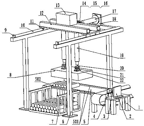
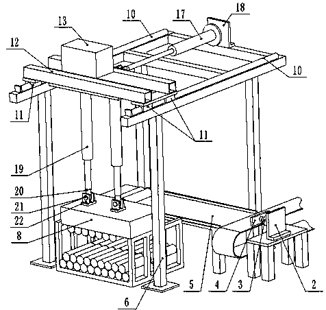
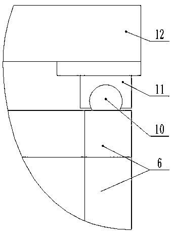
[0023] Such as figure 1 As shown, an automatic palletizing device includes a frame 6. The frame 6 has four legs at four corners. The four legs are fixedly connected to the ground with expansion bolts or anchor bolts. One cross brace is fixedly connected, and a guide rail 10 is respectively provided on the upper surface of the two cross braces, such as image 3 As shown, the cross section of the guide rail 10 is a superior arc shape, the plane of the superior arc shape is in contact with the cross brace, the two guide rails 10 are parallel, the two guide rails are both bolted to the cross brace, and the two guide rails 10 are slidably connected to the feeding mechanism;
[0024] A pump station 13 is provided on the feeding mechanism. One side of the feeding mechanism is connected to the piston rod of the second hydraulic cylinder 17, the tail of the second hydraulic cylinder 17 is connected to the third support 18, the third support 18 is connected to the frame 6, and the second hydraulic cylinder 17 Push the feeding mechanism to move along the guide rail 10. Two third hydraulic cylinders 19 are connected below the feeding mechanism. The piston rod of each third hydraulic cylinder 19 is connected to a magnetic device 8. A blanking platform 5 is provided under the magnetic device 8. The magnetic device 8 Push down the second hydraulic cylinder 17 to suck the bar on the blanking platform 5 and put it into the basket 7, which is located under the frame 6 and the guide rail 10. The magnetic device 8 is electrically connected to an external power source. The pump station 13 is in communication with the second hydraulic cylinder and the third hydraulic cylinder.
[0025] Specifically, the magnetic device 8 adopts an electromagnet, which has magnetism when energized, but disappears when it is cut off. The magnetic device 8 is bolted to a fourth support 22, the fourth support 22 is provided with a through hole, the center axis of the through hole is parallel to the rail 10, a second rotating shaft 21 is provided in the through hole, and the second rotating shaft 21 passes through the second The connecting piece 20 is rotatably connected with the second connecting piece 20, the second connecting piece 20 is provided with an internal threaded hole, and the head of the piston rod of the third hydraulic cylinder 19 is threadedly connected to the second connecting piece 20.
[0026] Specifically, the feeding mechanism includes a sliding seat 12 on which there are two rectangular tubes arranged in parallel. The pumping station 13 is fixedly connected to the two rectangular tubes, and a flat plate is welded on both ends of the two rectangular tubes. , The two sliding blocks 11 are bolted along the length of the guide rail 10 under each plate, the sliding block 11 is slidably connected to the guide rail 10, and the tail of the third hydraulic cylinder 19 is bolted under the middle of the two rectangular tubes; the middle position of the rectangular tube is vertical The rectangular tube is bolted to a second support 14 which is provided with a through hole. A first rotating shaft 15 is provided in the through hole. The first rotating shaft 15 passes through the first connecting member 16 and rotates with the first connecting member 16 For connection, the first connecting member 16 is provided with an internal threaded hole, and the head of the piston rod of the second hydraulic cylinder 17 is threadedly connected to the first connecting member 16.
[0027] The blanking platform 5 is located below the frame 6 near the side of the second hydraulic cylinder 17. The bar is placed on the blanking platform 5 in parallel to the guide rail 10, the blanking platform 5 is perpendicular to the guide rail 10, and one end of the blanking platform 5 is connected to the bar sawing device. The conveyor belts are connected, and a pushing device is provided on the other side of the conveyor belt facing the blanking platform 5, and the pushing device pushes the bar to the blanking platform 5;
[0028] Specifically, a first baffle 501 is welded or bolted on both sides of the blanking platform 5, the first baffle 501 is arranged perpendicular to the bar, the distance between the inner sides of the two first baffles 501 is greater than the length of the bar, and one end of the blanking platform 5 is welded Or a second baffle 502 is connected by bolts, both ends of the second baffle 502 are connected to the inner sides of the two first baffles 501, and the second baffle 502 is perpendicular to the first baffle 501. More specifically, the table surface of the blanking platform 5 is arranged obliquely, and the height of the end of the blanking platform 5 provided with the second baffle 502 is lower than the height of the end that is connected with the conveyor belt of the bar sawing device. The blanking platform 5 is inclined to facilitate the automatic rolling of the bar to the second baffle 502.
[0029] Specifically, the pushing device includes a base 1. The base 1 is fixed to the ground with expansion bolts or anchor bolts. A first support 2 is bolted on the base 1. The first support 2 is L-shaped, and the first support 2 is L-shaped. The straight bolts are connected to the first hydraulic cylinder 3, the head of the piston rod of the first hydraulic cylinder 3 is threadedly connected to the push plate 4, and the first hydraulic cylinder 3 is in communication with the pump station 13.
[0030] Specifically, a stop 9 is connected to the upper surface of the two transverse supports of the frame 6 respectively, and the stop 9 is connected to the end of the guide rail 10, and the stop 9 is higher than the guide rail 10. During installation and maintenance, the stopper 9 acts as a limit to the feeding mechanism and prevents the feeding mechanism from sliding down the guide rail 10.
[0031] Specifically, the basket 7 is made of welded steel, the basket 7 is U-shaped, and two lifting holes are respectively provided on the two vertical surfaces of the basket 7.
[0032] When the cut bar material is transported to one end of the conveyor belt, the piston rod of the first hydraulic cylinder 3 of the pushing device extends, driving the push plate 4 to push the bar material on the conveyor belt down the conveyor belt, and the bar material is in the thrust inertia and its own gravity. Under the action, it rolls to the lower end of the blanking platform 5 which is set inclinedly. There are first baffles 501 on both sides of the blanking platform 5 to prevent deviation of the bar during the rolling process. The second baffle 502 blocks the bars; when the number of bars on the blanking platform 5 is sufficient, the piston rod of the second hydraulic cylinder 17 contracts, the electromagnet under the sliding seat 12 is just above the bars, and the piston rod of the third hydraulic cylinder 19 Extend, the electromagnet reduces contact with the bar. Although the blanking platform 5 is tilted, the third hydraulic cylinder 19 and the electromagnet are rotatably connected, and the electromagnet can rotate around the second rotating shaft 21, so the electromagnet can be completely attached to the bar. The electromagnet is energized after the bar is attached, and the electromagnet attracts the bar. Such as figure 2 As shown, the piston rod of the second hydraulic cylinder 17 stretches, pushing the sliding seat 12 to move forward. When the sliding seat 12 reaches the top of the basket 7, the piston rod of the third hydraulic cylinder stretches, and the electromagnet descends. When the iron is powered off, the bar under the electromagnet falls into the material basket 7, then the piston rod of the third hydraulic cylinder 19 contracts, the electromagnet rises, the piston rod of the second hydraulic cylinder 17 contracts, and the slide 12 moves to the blanking platform 5 Above, prepare for the next action. During the moving and unwinding process of the electromagnet, the blanking table 5 has been continuously collecting bar materials to prepare for the electromagnet to attract the materials. After the bars in the basket 7 are full, they are lifted away with a crane, and the empty baskets can be replaced.
[0033] The above are only the preferred specific embodiments of the present invention, but the protection scope of the present invention is not limited to this. Anyone familiar with the technical field within the technical scope disclosed by the present invention, according to the technical solution of the present invention Equivalent replacements or changes to its inventive concept should all fall within the protection scope of the present invention.