

Auto-recovering reinforced column base and construction installation method thereof
An enhanced, self-resetting technology, applied in the direction of columns, piers, pillars, etc., can solve the problems of weakening self-resetting ability of composite composite springs and hindering the self-resetting of column feet, and achieves simple and convenient assembly, strong self-resetting effect, and excellent performance. The effect of auto-recovery ability
- Summary
- Abstract
- Description
- Claims
- Application Information
AI Technical Summary
Problems solved by technology
Method used
Image

Examples
Embodiment 1
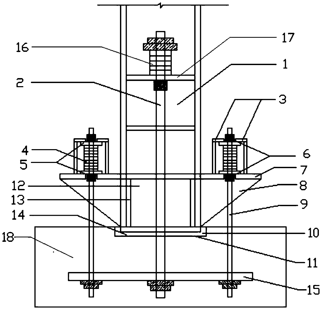
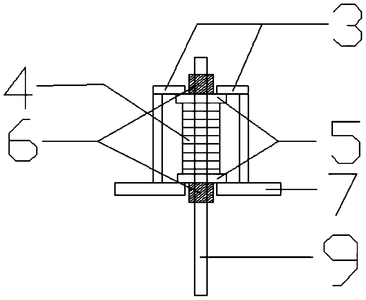
[0062] See attached figure 1 And attached figure 2 , the embodiment of the present invention discloses a self-resetting reinforced column foot, which is constructed on the foundation 18, including: a steel column 1, a high-strength tie rod 2, a cantilever plate 7, a limiting device 3, an anchor rod 9 and a limiting backing plate 5;
[0063] The steel column 1 is vertically arranged, and the bottom end is plugged into the limit groove 11 formed on the top surface of the foundation foundation 18;
[0064] The number of high-strength tie rods 2 is at least one, and it is arranged vertically. The bottom end is internally connected with the foundation 18. The rod body passes through the transverse stiffener 17 of the steel column 1 upwards, and the top of the transverse stiffener 17 and high-strength tie rod 2 is installed A disk spring group 16, and is fixed by the high-strength nut on the bottom surface of the transverse stiffener 17;
[0065] The cantilever plate 7 is horizo...
Embodiment 2
[0081] The embodiment of the present invention discloses a construction and installation method of a self-resetting reinforced column foot, which includes the following steps:
[0082] S1. Set the second disc spring group 4, two spacer backing plates 5 and two high-strength nuts 6 on the anchor rod 9, apply prestress to the second disc spring group 4 and connect the position limiting device 3 with the suspension The pick plate 7 is welded and fixed, and then the high-strength nut 6 is loosened, so that both sides of the limit backing plate 5 are stressed;
[0083] S2, welding and fixing the cantilever plate 7 and the side wall of the steel column 1, and welding the support plate 8 for support;
[0084] S3, set the first disc spring group 16 on the top of the high-strength tie rod 2 and apply prestress, and fix it by the high-strength nut on the bottom surface of the transverse stiffener 17;
[0085] S4. Pre-embed the casing for the passage of the high-strength tie rod 2 and t...
PUM
 Abstract
Description
Claims
Application Information