A charge structure of solid rocket motor with adjustable combustion surface ratio and rocket motor

A solid rocket and engine technology, applied in rocket engine devices, machines/engines, mechanical equipment, etc., can solve the problems that the thrust cannot be adjusted in a large range, the combustion surface ratio cannot be adjusted in a large range, etc., and achieve easy thrust design and large firepower coverage. Scope, easy-to-achieve effects

Active Publication Date: 2021-03-02
广州中科宇航探索技术有限公司
View PDF6 Cites 0 Cited by
  • Summary
  • Abstract
  • Description
  • Claims
  • Application Information

AI Technical Summary

Problems solved by technology

[0004] The purpose of this application is to provide a solid rocket motor charge structure and rocket motor with adjustable combustion-surface ratio, which solves the problems in the prior art that the combustion-surface ratio cannot be adjusted in a wide range, and the thrust cannot be adjusted in a wide range

Method used


Image

  • A charge structure of solid rocket motor with adjustable combustion surface ratio and rocket motor
  • A charge structure of solid rocket motor with adjustable combustion surface ratio and rocket motor
  • A charge structure of solid rocket motor with adjustable combustion surface ratio and rocket motor

Examples


Embodiment 1

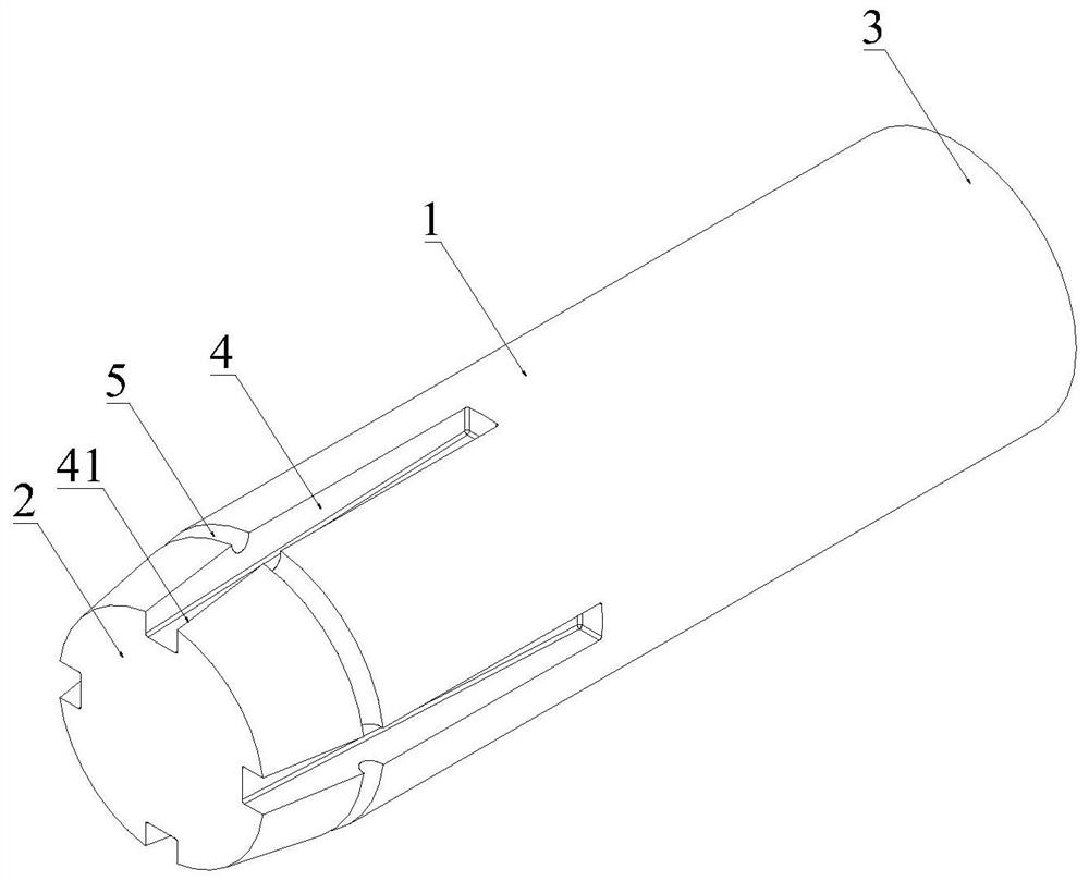
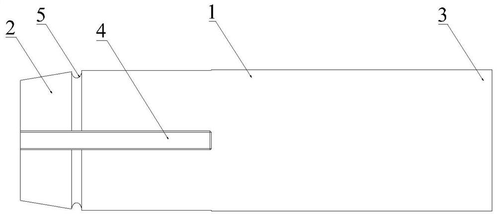
[0031] Such as Figure 1-3 As shown, the present application provides a solid rocket motor charge structure with adjustable combustion surface ratio, including: a charge body 1, a charge head 2 and a charge tail 3 integrally formed at both ends of the charge body 1, The charge body 1 is columnar, and the charge body 1 is a solid cylinder; the charge structure starts to burn from the outer surface of the charge head 2, and then burns the charge body 1 and the charge tail 3.

[0032] Such as figure 1 As shown, the charge head 2 is frustum-shaped, and the end of the charge head 2 with a larger diameter is connected to the charge body 1; the axial combustion of the charge structure is realized through the frustum-shaped charge head 2, and the shaft Combustion is burning from one end with a smaller diameter of the charge head 2 to an end with a larger diameter.

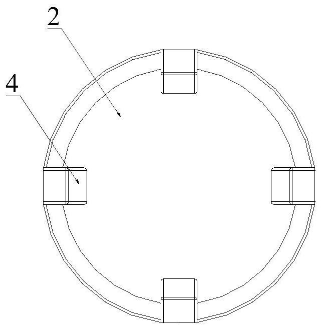
[0033] Such as figure 1 , figure 2 with image 3 As shown, the outer peripheral surface of the charge head 2 is ev...

Embodiment 2

[0061] A rocket motor, comprising a solid rocket motor charge structure with adjustable combustion surface ratio, and also includes a combustion chamber, a drug baffle and a nozzle, the solid rocket motor charge structure is arranged in the combustion chamber, the nozzle communicates with the combustion chamber, and the baffle The medicine plate is arranged at the junction of the nozzle and the combustion chamber.

[0062] The beneficial effect that this application realizes is as follows:

[0063] (1) The fuel-to-surface ratio of the charge structure of the present application can be adjusted to realize the reasonable distribution of the thrust of the solid rocket motor in the working time, and realize the dynamic characteristics of the single chamber and double thrust of the solid rocket motor. The solid rocket motor produces greater acceleration under the action of high thrust in the early stage of work, which can make the missile fly away quickly and avoid exposing the lau...


PUM


Abstract

The invention provides a combustion area ratio adjustable solid rocket engine charging structure and a rocket engine, and belongs to the technical field of solid rocket engines. The charging structurecomprises a charging body and further comprises a charging head part and a charging tail part which are integrally formed at the two ends of the charging body correspondingly, and the charging body is in a column shape. The charging head part is in a frustum shape, and accordingly axial combustion of the charging structure is achieved. A plurality of long-strip grooves are formed in the peripheral face of the charging head part in the axial direction of the charging head part at even intervals, and accordingly radial combustion of the charging structure is achieved. The multiple long-strip grooves extend to the charging body from the end portion, away from the charging body, of the charging head part. The combustion area ratio of the charging structure can be adjusted within a wide range,the thrust of the rocket engine is adjustable, the structure is simple, and the production cost is low.

Description

technical field [0001] The present application relates to the technical field of solid rocket motors, in particular to a solid rocket motor charge structure and a rocket motor with an adjustable fuel-to-surface ratio. Background technique [0002] At present, in the solid rocket motor, the gas generated by propellant combustion is discharged from the nozzle at high speed through the charge channel in the combustion chamber. Since the combustion chamber and the nozzle have different structural characteristics, the gas in the combustion chamber and the nozzle The flow of the gas also has different characteristics. There are solid propellant charge structure, ignition device and drug barrier in the combustion chamber. The solid propellant charge structure burns in the combustion chamber to become a gas with a certain pressure and temperature. At a certain flow rate, it enters the nozzle through the gas channel in the combustion chamber. In order to realize the large-scale adju...

Claims


Application Information

Patent Timeline
Patent Type & Authority Patents(China)
IPC IPC(8): F02K9/24
CPCF02K9/24
Inventor 张翔赖谋荣布向伟李秦峰史晓宁杨毅强
Owner 广州中科宇航探索技术有限公司
Why Eureka
Try Eureka