Eureka AIR delivers breakthrough ideas for toughest innovation challenges, trusted by R&D personnel around the world.

Measuring device for measuring orifice chamfer angle

A technology for measuring devices and measuring holes, which is applied in the direction of measuring devices, mechanical measuring devices, and mechanical devices, etc., can solve the problem that the measuring device cannot easily and quickly measure the chamfering angle of the workpiece hole, so as to facilitate manufacturing and improve convenience Sexuality and ease of production

Inactive Publication Date: 2020-04-28
河南航天精工制造有限公司
View PDF10 Cites 0 Cited by
  • Summary
  • Abstract
  • Description
  • Claims
  • Application Information

AI Technical Summary

Problems solved by technology

[0004] The purpose of the present invention is to provide a measuring device for measuring the chamfering angle of the orifice, so as to solve the technical problem that the measuring device in the prior art cannot measure the chamfering angle of the workpiece orifice simply and quickly

Method used


Image

  • Measuring device for measuring orifice chamfer angle
  • Measuring device for measuring orifice chamfer angle

Examples


Embodiment 1

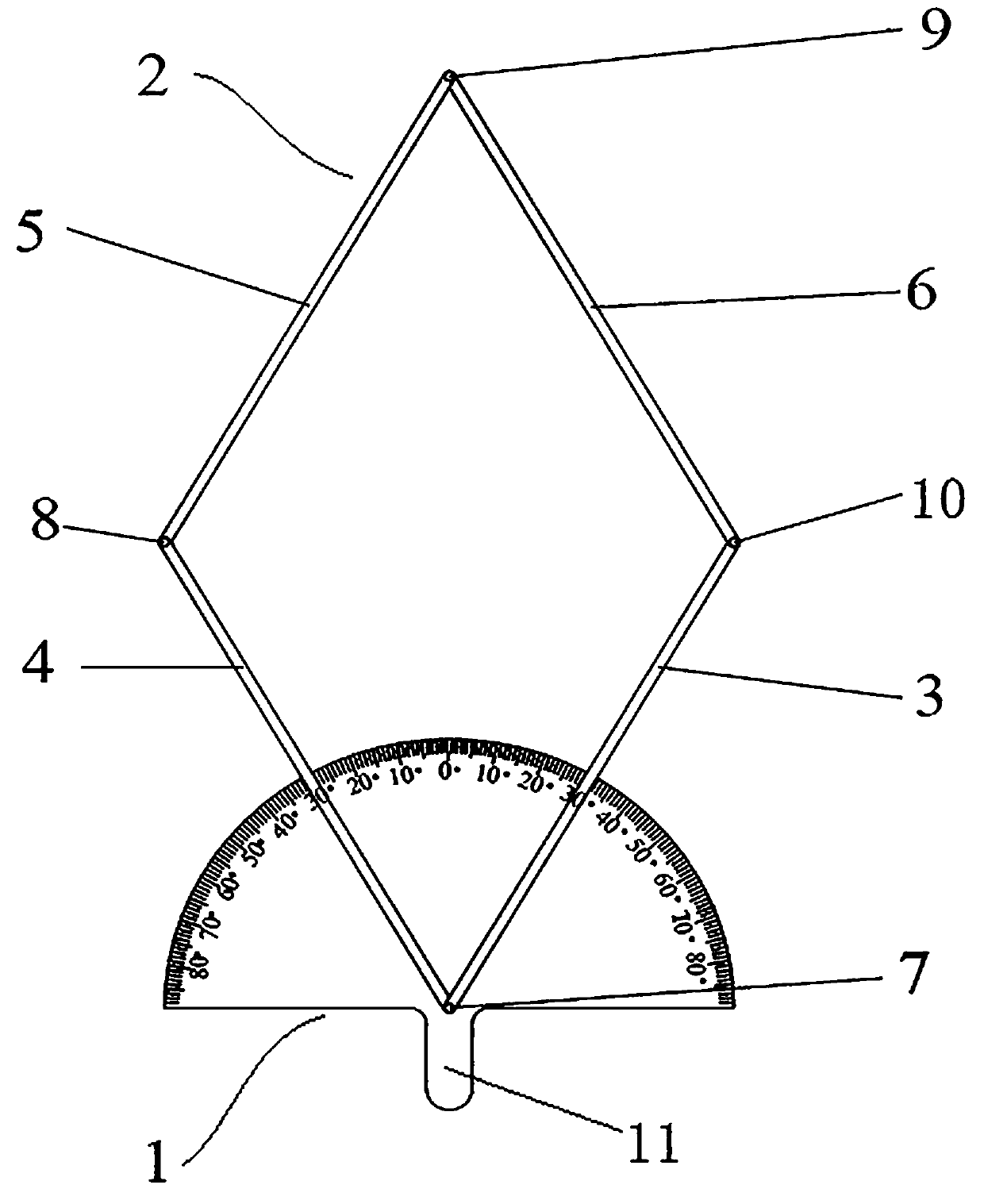
[0027] Specific embodiment 1 of the measuring device of the measuring orifice chamfering angle of the present invention: as figure 1 As shown, the measuring device includes a protractor 1 and a measuring stand 2 .

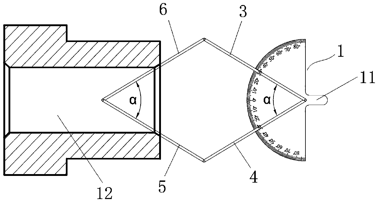
[0028] The measuring frame 2 is a planar four-bar linkage, including a first link 3, a second link 4, a third link 5 and a fourth link 6. The four links have equal lengths and are hinged from head to tail in turn. Wherein, the hinge axis between the first and second connecting rods is the first hinge axis 7, the hinge axis between the second and third connecting rods is the second hinge axis 8, and the hinge axis between the third and fourth connecting rods is The third articulated shaft 9 , the articulated shaft between the fourth and the first connecting rod is the fourth articulated shaft 10 .

[0029] While the first hinge shaft 7 realizes the hinged connection between the first and second connecting rods, it is also installed on the protractor 1 perpendicular...


PUM


Abstract

The invention relates to a measuring device for measuring an orifice chamfer angle. The measuring device comprises a protractor. A measuring frame is a parallelogram-shaped plane four-bar linkage, theprotractor is installed at the hinge point of the two connecting bars and can rotate relative to at least one of the two connecting bars, the protractor is parallel to the plane where the plane four-bar linkage is located, and the original point of the protractor is located on the hinge axis of the two connecting bars. The two connecting rods, back on to the protractor, of the measuring frame serve as measuring rods and are used for being inserted into measured workpiece holes; the two measuring rods are attached to the chamfered inclined face in the inclination direction of the chamfered inclined face of the measured workpiece after being opened, and the axis of the measured workpiece hole is located on the plane where the planar four-bar linkage is located; two connecting bars, connected with the protractor, of the measuring frame serve as indicating rods, and an operator determines the included angle between the two indicating rods according to the scales, aligned with the indicating rods, of the protractor. The measuring rods extend into the measured workpiece holes to be attached to the chamfered inclined face, the included angle between the two indicating rods is read, so that the chamfering angle value of the hole opening of the workpiece is conveniently and rapidly measured.

Description

technical field [0001] The invention relates to a measuring device for measuring the chamfering angle of an orifice. Background technique [0002] In mechanical processing, when parts with holes are produced, they will be chamfered at the hole to remove sharp corners and burrs, so as to reduce stress concentration and heat treatment deformation of the workpiece, prevent bumping, and facilitate the insertion of parts into the hole during assembly. [0003] In the actual processing process, the chamfer has certain size requirements, but since the chamfer of the hole is located inside the workpiece, if the projection method is used to measure the chamfer of the hole, it cannot be measured directly. It is necessary to cut the product and measure it under the projection. The method is a destructive measurement method, which is not easy to implement. Or use a profiler for measurement, but the measurement process using a profiler is cumbersome, affects production efficiency, and c...

Claims


Application Information

Patent Timeline
Patent Type & Authority Applications(China)
IPC IPC(8): G01B5/24G01B5/00
CPCG01B5/0004G01B5/24
Inventor 张红军张松松张兵点穆延兵董新燕胡秀娟许永强
Owner 河南航天精工制造有限公司
Why Eureka
Eureka Blog
Learn More