A flow continuous calibration system and method for a high-temperature gas regulator

A calibration method and a calibration system technology are applied in the field of continuous flow calibration system of high temperature gas regulators, which can solve the problems of high test cost and complicated test process, achieve low cost, simple test method, and reduce the number of ignitions and the number of supporting products. Effect

Active Publication Date: 2021-07-20
XIAN AEROSPACE PROPULSION INST
View PDF9 Cites 0 Cited by
  • Summary
  • Abstract
  • Description
  • Claims
  • Application Information

AI Technical Summary

Problems solved by technology

[0004] In order to solve the problem of obtaining the flow characteristics of the gas control valve under the real medium in the ground assessment test in the background technology, only a single working point test can be carried out, and each test must be ignited by a separate gas generator to obtain high-temperature and high-pressure oxygen-enriched gas, resulting in the test For the problems of too much cost and complicated test process, the present invention provides a flow continuous calibration system and method for high-temperature gas regulators, which greatly simplifies the calibration test system and operation process

Method used


Image

  • A flow continuous calibration system and method for a high-temperature gas regulator
  • A flow continuous calibration system and method for a high-temperature gas regulator
  • A flow continuous calibration system and method for a high-temperature gas regulator

Examples


Embodiment Construction

[0036] In order to make those skilled in the art understand the technical solutions of the present invention more clearly and accurately, the present invention will be further described below in conjunction with the accompanying drawings and specific embodiments.

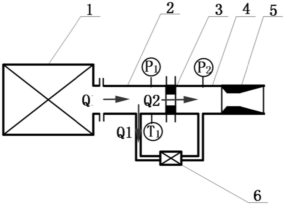
[0037] Such as figure 1 As mentioned above, this embodiment provides a flow continuous calibration system for a high temperature gas regulator, including a gas generator 1, a main pipeline 2, a branch pipeline 4, a throttle coil 3, an outlet throat pipe 5, a pressure sensor, a temperature Sensor and gas regulator 6; the gas outlet of the gas generator 1 is installed with a main pipeline 2, and the main pipeline 2 is provided with a throttle ring 3 and an outlet throat pipe 5 in sequence along the direction of gas flow; the inlet of the branch pipeline 4 is connected to the gas On the main pipeline 2 between the generator 1 and the throttle ring 3, the outlet of the branch pipeline 4 is connected to the main pipeline...


PUM


Abstract

The invention discloses a system and method for continuously calibrating the flow rate of a high-temperature gas regulator. In the system, the gas outlet of the gas generator is installed with a main pipeline, and the main pipeline is sequentially provided with a throttling ring and an outlet throat pipe along the gas flow direction; The inlet of the branch pipeline is connected to the main road between the gas generator and the throttle ring, and the outlet of the branch pipeline is connected to the main road between the throttle ring and the outlet throat pipe; the gas regulator to be calibrated is installed on the branch pipe On the road; there are two pressure sensors, located on the inlet side and outlet side of the throttle ring respectively; the temperature sensor is located on the inlet side of the throttle ring. The invention utilizes the characteristic that the inlet and outlet pressure ratios of the gas regulator under the real working conditions of the engine are equivalent to the inlet and outlet pressure ratios of the gas regulator in the ground test system, simplifies the calibration steps of the flow coefficient of the gas generator, and effectively reduces the The number of ignition times and the number of supporting products required for the calibration process of the gas regulator are low in cost.

Description

technical field [0001] The invention belongs to the field of aerospace technology, and in particular relates to a flow continuous calibration system and method for a high-temperature gas regulator Background technique [0002] In order to achieve a wide range of operating conditions for high-pressure afterburning cycle engines, it can be realized by setting a gas regulator in the gas circuit. At this time, due to the particularity of the working medium, there are significant differences in the thermodynamic properties of the ground cold air and hot air and the real gas, and the characteristic relationship between the gas regulator's rotation angle, flow rate and pressure drop obtained through the ground air is quite different from that of the real medium. [0003] In order to achieve precise adjustment of engine thrust, the flow characteristics of the gas control valve in real media must be obtained in the ground assessment test. Under ideal conditions, it is necessary to s...

Claims


Application Information

Patent Timeline
Patent Type & Authority Patents(China)
IPC IPC(8): G01M13/003
CPCG01M13/003
Inventor 巨龙高玉闪邢理想马键武晓欣李春红刘伟
Owner XIAN AEROSPACE PROPULSION INST
Why Eureka
Try Eureka