Reaction cup lifting and rotating device and transfer mechanism

A technology for lifting, rotating and rotating mechanisms, applied in the field of medical devices, can solve the problems of easy damage of rotating mechanisms, complicated control circuits, and increased maintenance costs, and achieve the effect of reducing the depreciation speed, the range of lifting or rotating, and reducing maintenance costs.

Pending Publication Date: 2020-04-28
中科精瓒(武汉)医疗技术有限公司
View PDF0 Cites 1 Cited by
  • Summary
  • Abstract
  • Description
  • Claims
  • Application Information

AI Technical Summary

Problems solved by technology

At present, in the existing medical automation or semi-automation equipment, the transfer of cuvettes is realized by lifting and rotating two independent transport mechanisms, which takes up a lot of space, and the lifting and rotating transport mechanisms need to work in coordination, and the corresponding control circuits are relatively It is more complicated; in addition, there is also a transport mechanism that can lift and rotate at the same time. The rotating mechanism is connected to the lifting mechanism, and the rotating mechanism is connected to the manipulator for grabbing the cuvette. Then drive the manipulator to move up and down. After long-term operation, the rotating mechanism is easily damaged, which increases maintenance costs

Method used


Image

  • Reaction cup lifting and rotating device and transfer mechanism
  • Reaction cup lifting and rotating device and transfer mechanism
  • Reaction cup lifting and rotating device and transfer mechanism

Examples


Embodiment 1

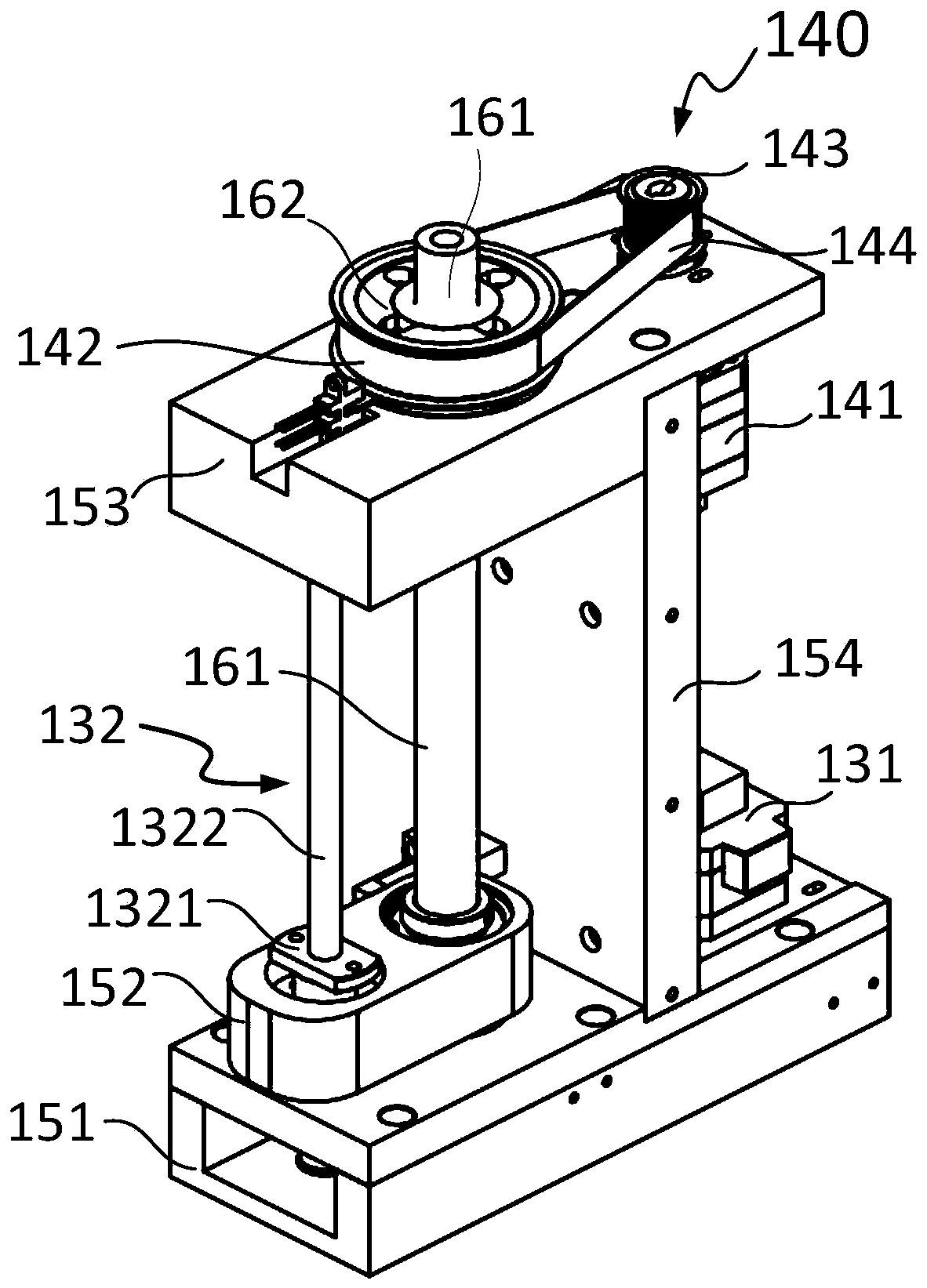
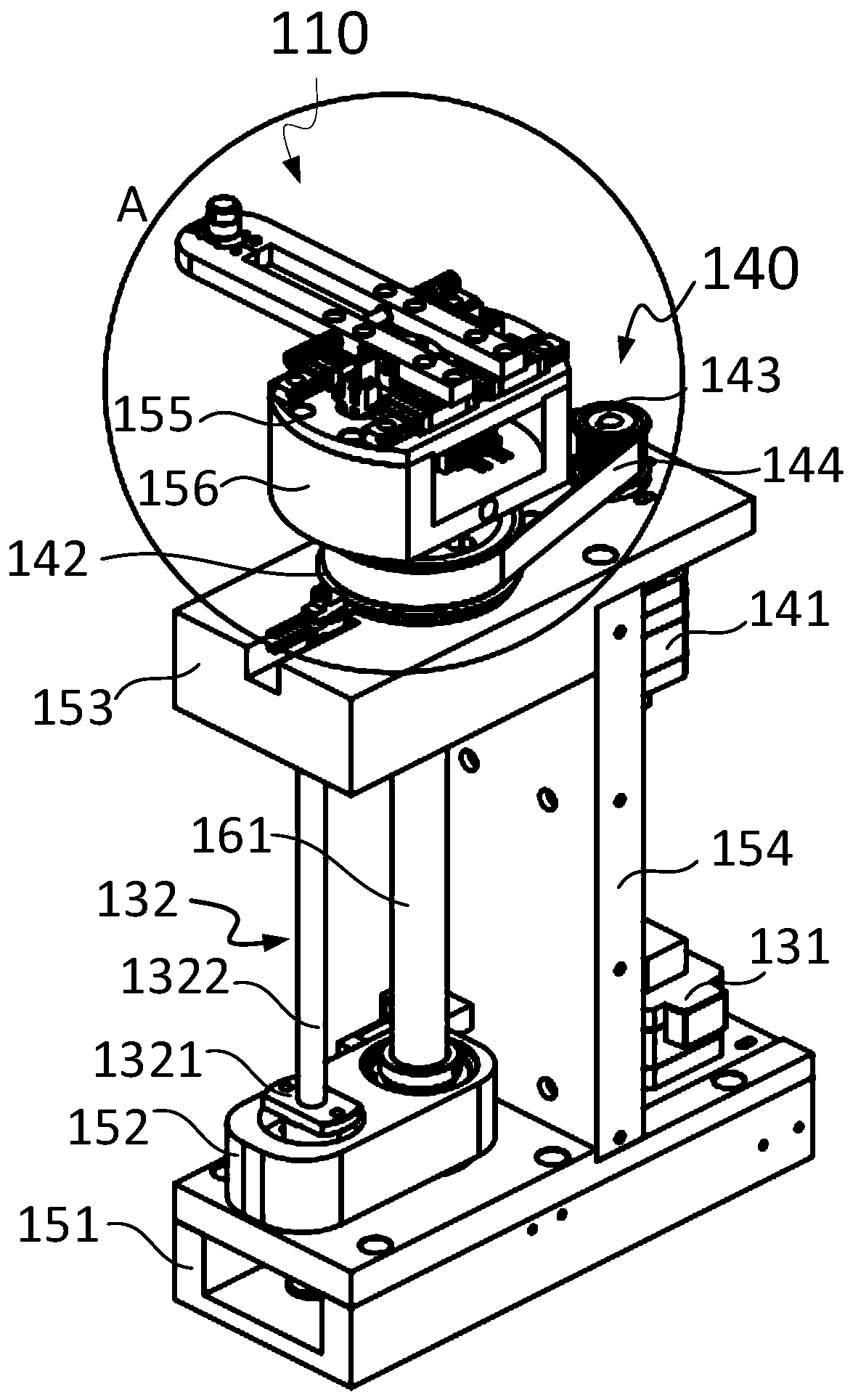
[0042] Such as Figure 1 to Figure 5As shown, the present invention provides a cuvette lifting and rotating device, which includes a lifting and rotating device body connected to a manipulator body 110 for grabbing a cuvette 200. The lifting and rotating device body includes a lifting mechanism 130 and a rotating mechanism 140. . A spline coupling assembly 160, the spline coupling assembly 160 includes a spline shaft 161 provided with a keyway and a rotating member 162 provided with a keyway, the rotating member 162 is sleeved on the outside of the spline shaft 161, the One end of the spline shaft 161 is connected with the lifting mechanism 130, the other end is used for connecting with the manipulator body 110, and the rotating mechanism 140 is connected with the rotating member 162; wherein,

[0043] The lifting mechanism 130 drives the spline shaft 161 to reciprocate axially in the rotating member 162, the rotating mechanism 140 drives the rotating member 162 to rotate, and...

Embodiment 2

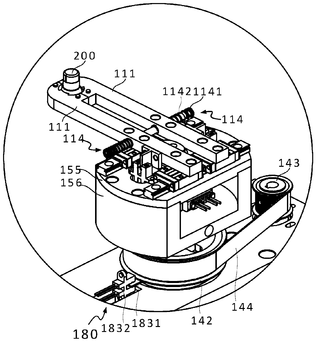
[0053] Such as Figure 2 to Figure 7 As shown, the present invention also provides a cuvette transfer mechanism, including a manipulator body 110, a lifting and rotating device body as described in Embodiment 1, and a spline coupling assembly 160 between the manipulator body 110 and the lifting and rotating device body The spline shaft 161 is connected.

[0054] The manipulator body 110 includes two opposing jaws 111, a rotating device, a cam 113, two guide rails 115, and four sliders 116. One end of the two jaws 111 is provided with a clamp for grabbing the cuvette 200. The holding area 1111, the two jaws 111 are respectively connected with two sliders 116, and each guide rail 115 is respectively slidably connected with a slider 116 connected to the two jaws 111, and the outer sides of the two jaws 111 are respectively provided with reset members; wherein,

[0055] Described cam 113 is positioned at the middle of two jaws 111, and the length and width of described cam 113 ar...


PUM


Abstract

The invention provides a reaction cup lifting and rotating device. The lifting and rotating device comprises a lifting and rotating device body connected with a manipulator body, the lifting and rotating device body comprises a lifting mechanism, a rotating mechanism and a spline connecting assembly, one end of a spline shaft of the spline connecting assembly is connected with the lifting mechanism, the other end is used for being connected with the manipulator body, and the rotating mechanism is connected with a rotating piece of the spline connecting assembly; and the lifting mechanism drives the shaft to do reciprocating motion in the rotating piece, the rotating mechanism drives the rotating piece to rotate, then the shaft is driven to rotate so as to drive the manipulator body to do lifting or rotating motion, and transportation of a reaction cup is achieved. The invention further provides a reaction cup transfer mechanism. The spline connecting assembly is cooperated with the lifting mechanism and the rotating mechanism to achieve lifting or rotating motion, the lifting motion and the rotating motion are separately and independently performed, during the lifting motion, the rotating mechanism is kept still, a depreciation speed of the rotating mechanism is reduced, maintenance cost is reduced, and an occupied space is small.

Description

technical field [0001] The invention relates to the technical field of medical devices, in particular to a cuvette lifting and rotating device and a transfer mechanism. Background technique [0002] In the medical field, it is essential to detect blood, body fluids, etc. These blood, body fluids, etc. are usually collected and placed in cuvettes, and then further operations such as dosing, separating, diluting, and testing are performed. [0003] The above-mentioned liquid preparation, liquid separation, dilution, detection and other operations are generally carried out by automatic or semi-automatic equipment. When the equipment is working, it is necessary to transfer the cuvettes in different working areas. In order to grab and transfer cuvettes to other places, the manipulator usually involves lifting and rotating movements. At present, in the existing medical automation or semi-automation equipment, the transfer of cuvettes is realized by lifting and rotating two indep...

Claims


Application Information

Patent Timeline
Patent Type & Authority Applications(China)
IPC IPC(8): G01N35/00
CPCG01N35/00
Inventor 王钟周孙海旋吕丹辉李俊坡杨森闫雪松王一凡周虎军李冬柴阔
Owner 中科精瓒(武汉)医疗技术有限公司
Why Eureka
Try Eureka