A Method of Aerodynamic Shape Optimization Based on Flow Field Prediction

A technology of aerodynamic shape and optimization method, applied in the direction of constraint-based CAD, design optimization/simulation, instrument, etc., can solve the design quality dependence, the data information cannot be fully utilized, and weaken the ability of the proxy model to capture the essential characteristics of the real model, etc. It can improve the convergence speed and overall efficiency, avoid sampling and simulation calculation, and save the cost of optimization time.

Active Publication Date: 2021-05-28
NAT UNIV OF DEFENSE TECH
View PDF0 Cites 0 Cited by
  • Summary
  • Abstract
  • Description
  • Claims
  • Application Information

AI Technical Summary

Problems solved by technology
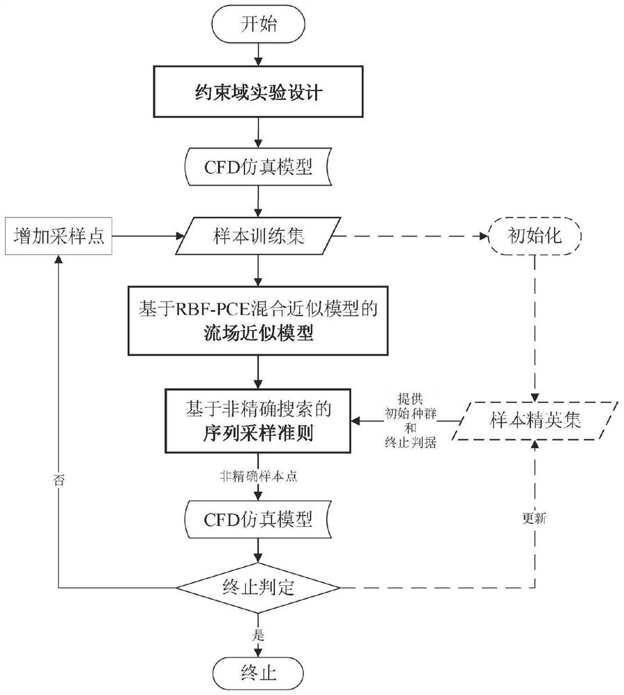
This method has the following disadvantages: 1) The determination of the target flow field distribution requires the designer to have a deep understanding of the design target and rich design experience, and the design quality depends heavily on the selection of the target aerodynamic characteristics; 2) It is difficult to deal with the aerodynamic , geometric constraints, and performance constraints at non-design points
This method has the following defects: 1) The biggest limitation of the gradient-based optimization method is that it is easy to fall into the local optimum and it is difficult to find the global optimum. To a certain extent, it limits its scope of application and further development; 2) Due to its random search characteristics, heuristic algorithms generally have the characteristics of slow convergence speed, and the optimization process requires thousands of iterations of the calculation model. For engineering optimization problems requiring high precision, combining time-consuming simulation models will make the amount of calculation unacceptable, which is also the biggest obstacle to the application of heuristic algorithms in engineering, which greatly limits the scope of application; 3) Based on proxy models (also known as approximate Model Surrogate Model, or Metamodel) optimization method, using an approximate model with high computational efficiency instead of a high-precision simulation model, effectively improving the efficiency of optimization design
In this process, the simulation model is regarded as a "black box", and the approximate model only predicts the input-output relationship of the "black box", which cannot make full use of the large amount of data information generated by the time-consuming simulation model, which seriously weakens the ability of the proxy model to capture the real The ability of the essential characteristics of the model greatly limits the further improvement of the efficiency of the approximate optimization method; for specific engineering optimization problems, such as the aerodynamic design optimization problem, it is a further step to fully utilize the simulation data through the strong coupling between the approximate optimization method and the calculation model. An Efficient Way to Tap the Efficiency Potential of Approximate Optimization Methods

Method used


Image

  • A Method of Aerodynamic Shape Optimization Based on Flow Field Prediction
  • A Method of Aerodynamic Shape Optimization Based on Flow Field Prediction
  • A Method of Aerodynamic Shape Optimization Based on Flow Field Prediction

Examples


Embodiment 1

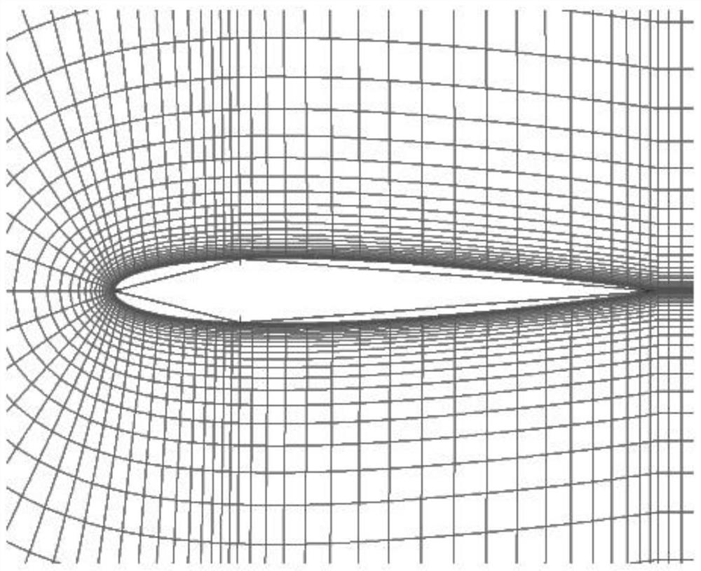
[0081] Regarding the optimization of the benchmark problem NACA-0012 airfoil, the optimization problem is in the inviscid free flow, the Mach number is 0.85 Ma, and the flight state of 0° angle of attack is the optimization of the resistance minimization, and the thickness of the airfoil is constrained. The optimization problem is expressed as follows:

[0082] minimize C D

[0083]

[0084] Among them, C D is the drag coefficient, y is the geometric thickness of the optimized airfoil, y baseline is the geometric thickness of the initial airfoil, x is the abscissa;

[0085] The optimization object NACA-0012 airfoil is defined as follows:

[0086]

[0087] About the model:

[0088] According to the requirements of the optimization problem, the inviscid flow model is adopted. In this case, the viscosity is not considered, and the airfoil resistance is all from the pressure difference resistance, and the viscous resistance is 0.

[0089] Regarding boundary conditions: ...

Embodiment 2

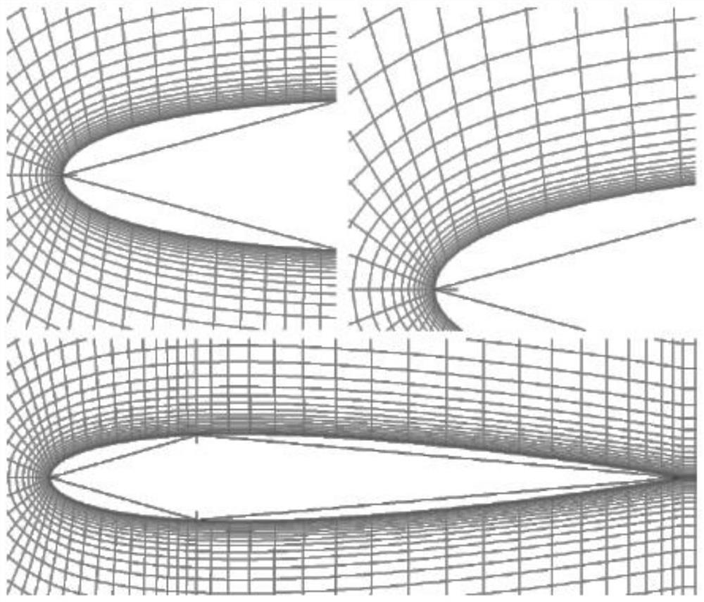
[0111] Regarding the optimization of the shape of the fairing, the basic shape of this example is the fairing. The optimization problem is a drag minimization optimization at a height of 10.1 km and a speed of Mach 1.8 under volume and heat flux constraints. Specifically, the constraints are that the volume of the optimized shape is not smaller than the volume of the basic shape, and the maximum heat flow on the surface is not greater than the maximum heat flow on the surface of the baseline. In summary,

[0112] The optimization problem is formulated as follows:

[0113] minimize C D

[0114] subject to: F≤F baseline

[0115] V≥V baseline

[0116] Among them, F is the maximum heat flux density on the surface of the fairing, V is the volume of the fairing, and F baseline is the maximum heat flux density on the fairing surface of the base airfoil, V baseline is the fairing volume of the base airfoil;

[0117] About the model: In this example, the Spalart-Allmaras (S-A...


PUM


Abstract

The invention discloses an aerodynamic shape optimization method based on flow field prediction, which directly approximates the flow field pressure distribution, proposes a flow field approximation model deeply coupled with the aircraft aerodynamic optimization problem, and realizes the generation of a high-precision flow field simulation model The high-efficiency use of a large amount of flow field data reduces the number of high-precision model simulation calls of the sequence approximation optimization method, improves the quality and efficiency of aircraft aerodynamic shape optimization, and greatly improves the optimization efficiency of engineering optimization problems. And by comparing with conventional sequence approximate optimization method and stochastic evolution algorithm, the validity and high efficiency of the method of the present invention are verified. The aerodynamic shape optimization method provided by the present invention has important application value for the refined design of aircraft aerodynamic shape.

Description

technical field [0001] The invention relates to the technical field of aircraft aerodynamic shape optimization design, in particular to an aerodynamic shape optimization method based on flow field prediction. Background technique [0002] Aerodynamic shape design is an important part of aircraft design and has an important impact on overall performance. With the improvement of aircraft performance requirements, the design of aircraft becomes more complex, which puts forward higher requirements for the fine design of aerodynamic layout. The traditional aerodynamic engineering estimation model is difficult to apply in many occasions, and high-precision numerical simulation is imperative; the traditional evolutionary algorithm usually requires thousands of iterations, which is unacceptable for the time-consuming high-precision simulation model, and the approximate optimization method came into being , in order to achieve a balance between aerodynamic design accuracy and effici...

Claims


Application Information

Patent Timeline
Patent Type & Authority Patents(China)
IPC IPC(8): G06F30/15G06F30/17G06F30/20G06F111/04G06F119/14
CPCY02T90/00
Inventor 王东辉王文杰武泽平彭博张为华向敏彭科
Owner NAT UNIV OF DEFENSE TECH
Why Eureka
Try Eureka