
Tool clamp and surface roughness test device

A technology of tooling fixtures and clamping arms, which is applied in the field of tooling fixtures and surface roughness testing devices, and can solve problems such as inaccurate data measurement, high labor intensity, and poor applicability

Pending Publication Date: 2020-05-01
广东康派环创科技有限公司
View PDF0 Cites 0 Cited by
  • Summary
  • Abstract
  • Description
  • Claims
  • Application Information

AI Technical Summary

Problems solved by technology

[0003] Based on this, it is necessary to provide a tooling fixture and a surface roughness testing device, aiming to solve the problems of high labor intensity, inaccurate data measurement and poor applicability in the prior art

Method used


Image

  • Tool clamp and surface roughness test device

Examples


Embodiment Construction

[0025] In order to make the object, technical solution and advantages of the present invention clearer, the present invention will be further described in detail below in conjunction with the accompanying drawings and specific implementation methods. It should be understood that the specific embodiments described here are only used to explain the present invention, and do not limit the protection scope of the present invention.

[0026] It should be noted that when an element is referred to as being “fixed on”, “disposed on” or “installed on” another element, it may be directly on the other element or there may be an intervening element. When an element is considered to be "connected" to another element, it may be directly connected to the other element or there may be an intervening element at the same time; the specific way that one element is fixedly connected to another element can be realized through existing technologies, and will not be discussed here. To repeat it agai...


PUM


Abstract

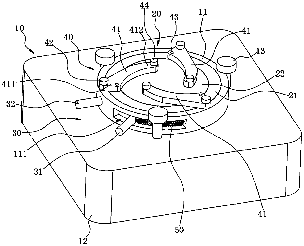
The invention relates to a tool clamp and a surface roughness test device. The tool clamp comprises a fixed base, a rotating base, a driving mechanism and a clamping mechanism. The rotating base is rotatably mounted on the fixed base, the driving mechanism is arranged on the rotating base and is used for driving the rotating base to rotate relative to the fixed base, the clamping mechanism at least comprises three clamping arms and a transmission assembly, the clamping arms are in rotatable connection with the rotating base through the transmission assembly, the clamping arms can synchronouslyand mutually rotate to be close to each other or rotate to be away from each other, when buttons needed to be clamped and fixed are different in size, amplitudes, for rotating to be away from each other, of the clamping arms only need to be correspondingly adjusted, the areas between the clamping arms can be adjusted, it is ensured that the buttons can be placed between the clamping arms, the clamping and fixing needs can be met, and adaptation is high.

Description

technical field [0001] The invention relates to the field of fixtures, in particular to a tooling fixture and a surface roughness testing device. Background technique [0002] In order to improve the user experience, in the garment manufacturing industry, it is usually necessary to test the surface roughness of buttons to provide data support for the improvement of the button forming manufacturing process. During the test, slide the probe of the roughness tester over the surface of the button to achieve the purpose of testing and collecting data. In order to ensure the accuracy of the test results, it is necessary to ensure that the button is fixed. At present, there are two commonly used methods of fixing buttons: one is that the worker manually presses the button with one hand and does not move, and uses the probe to test with the other hand. The long-term work of the workers not only has high labor intensity, but also leads to the labor force of the enterprise. When the ...

Claims


Application Information

Patent Timeline
IPC IPC(8): B25B11/00G01B21/30
CPCB25B11/00G01B21/30
Inventor 蔡佳翊盛峭敏谭永权李子庆
Owner 广东康派环创科技有限公司
Learn More