
Electric C-shaped nail gun

A nail gun and electric technology, applied in nailing tools, nailing staple tools, manufacturing tools, etc., can solve the problems of C-shaped nails offset, poor running stability, and frustration, and avoid jamming and deviation. The effect of moving, running smoothly, and preventing occlusal deformation

Inactive Publication Date: 2020-05-01
陶成斌
View PDF0 Cites 2 Cited by
  • Summary
  • Abstract
  • Description
  • Claims
  • Application Information

AI Technical Summary

Problems solved by technology

The existing C-shaped nail gun is a pneumatic nail gun, which is an automatic nail clamping device. The C-shaped nail is driven by a high-pressure air cylinder to clamp the C-shaped nail on the object through the gun mouth. However, the pneumatic nail gun has the following defects: the cylinder There is a sense of frustration during the horizontal reciprocating driving process, and the running stability is poor. Therefore, in the process of pushing the C-shaped nails due to the change of its driving force, the C-shaped nails are easy to shift. When the deviation is large, the C-shaped nails are stuck in the nail gun. At the exit end of the nail gun, and when the offset is small, the clamping ring formed by the C-shaped nail deforms after the exit end of the nail gun is clamped. The unstable operation of the driving force will also make the C-shaped nail pop out of the exit end of the nail gun. risky

Method used


Image

  • Electric C-shaped nail gun
  • Electric C-shaped nail gun
  • Electric C-shaped nail gun

Examples


Embodiment approach

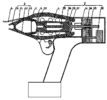
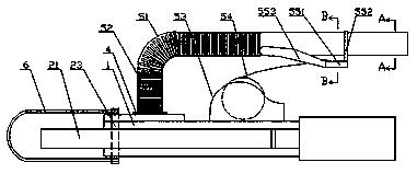
[0032] Such as figure 1 It shows an embodiment of an electric C-shaped nail gun of the present invention, including a gun housing 1, a clamp mechanism 2 and a driving mechanism 3 inside the gun housing 1, and one side of the gun housing 1 has a C-shaped nail 52 embedded in it. One end of the driving mechanism 3 is in contact with the C-shaped nail 52 and pushes the C-shaped nail 52 to move toward the outlet end of the clamp mechanism 2, and the outlet end of the clamp mechanism 2 gradually expands with the push of the driving mechanism 3 , the outlet end of the clamp mechanism 2 gradually gathers together with the contraction of the drive mechanism 3;

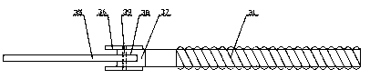
[0033] The driving mechanism 3 includes a screw mandrel 31, a motor 32, a first helical gear 33, a second helical gear 34, and a push block 35. The rotation of the motor 32 drives the first helical gear 33 and the second helical gear 34 meshing with each other to rotate so as to realize the rotation of the screw mandrel. 31 ho...


PUM


Abstract

The invention relates to an electric C-shaped nail gun which comprises a gun shell. A clamping mechanism and a drive mechanism are arranged in the gun shell; an inlet end for a C-shaped nail to be embedded is arranged on one side of the gun shell; one end of the drive mechanism contacts the C-shaped nail and pushes the C-shaped nail to move toward an outlet end of the clamping mechanism; the outlet end of the clamping mechanism is expanded step by step along with the pushing of the drive mechanism; the outlet end of the clamping mechanism is gathered together step by step along with the contraction of the drive mechanism; the drive mechanism comprises a screw rod, a motor, a first bevel gear, a second bevel gear and a push block; the motor rotates to drive the first bevel gear and the second bevel gear meshing with each other to rotate, so that the transmission of the screw rod in the horizontal direction is realized; one end of the screw rod is fixedly connected with one end of the push block; rolling wheels distributed up and down are arranged on two sides of the end of the screw rod; and the other end of the push block pushes the C-shaped nail to move toward the outlet end of the clamping mechanism along with the transmission of the screw rod. The electric C-shaped nail gun provided by the invention has the following advantages of stability in driving, and capabilities on avoiding stoppage and deviation of the C-shaped nail and preventing occlusion and deformation.

Description

Technical field: [0001] The invention belongs to the field of electric tools, and in particular relates to an electric C-shaped nail gun. Background technique: [0002] The C-type nail gun has the advantages of fast nail clamping speed, firm nail clamp, and convenient use. It is widely used in bed net production, car seat cushion production, breeding cage production, fence production and other industries. The existing C-shaped nail gun is a pneumatic nail gun, which is an automatic nail clamping device. The C-shaped nail is driven by a high-pressure air cylinder to clamp the C-shaped nail on the object through the gun mouth. However, the pneumatic nail gun has the following defects: the cylinder There is a sense of frustration during the horizontal reciprocating driving process, and the running stability is poor. Therefore, in the process of pushing the C-shaped nails due to the change of its driving force, the C-shaped nails are easy to shift. When the deviation is large, t...

Claims


Application Information

Patent Timeline
Patent Type & Authority Applications(China)
IPC IPC(8): B25C5/15B25C5/02B25C7/00
CPCB25C5/02B25C5/15B25C7/00
Inventor 陶成斌
Owner 陶成斌
Learn More