Three-dimensional active gravity unloading device suitable for multi-degree-of-freedom experimental object

An experimental object, gravity unloading technology, applied in the field of microgravity simulation, can solve the problems of poor motion stability and inability to realize multi-point hanging, and achieve the effect of expanding the scope of use

Active Publication Date: 2020-05-01
HARBIN INST OF TECH
View PDF11 Cites 11 Cited by
  • Summary
  • Abstract
  • Description
  • Claims
  • Application Information

AI Technical Summary

Problems solved by technology

[0004] The present invention aims to solve the problem of poor motion stability of existing microgravity simulation devices and the inability to realize multi-point suspension, and further provides a three-dimensional active gravity unloading device suitable for multi-degree-of-freedom experimental objects

Method used


Image

  • Three-dimensional active gravity unloading device suitable for multi-degree-of-freedom experimental object
  • Three-dimensional active gravity unloading device suitable for multi-degree-of-freedom experimental object
  • Three-dimensional active gravity unloading device suitable for multi-degree-of-freedom experimental object

Examples


specific Embodiment approach 1

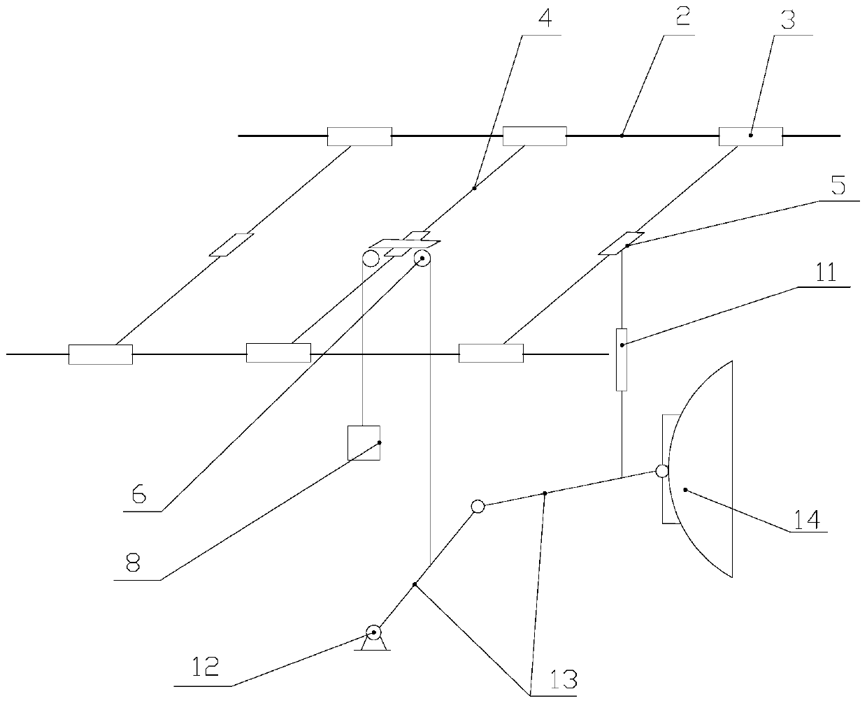
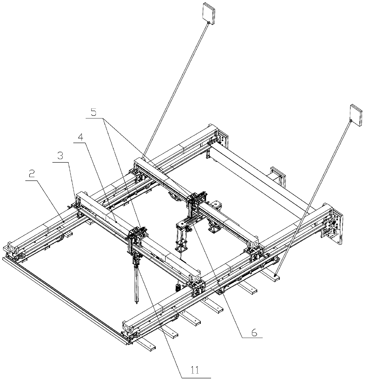
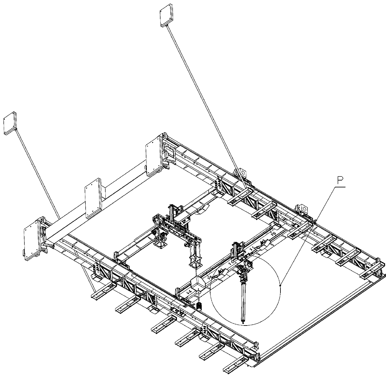
[0023] Specific implementation mode one: combine Figure 1~5 Description of this embodiment, a three-dimensional active gravity unloading device suitable for multi-degree-of-freedom experimental objects, which includes a load-bearing frame, an electric cylinder type unloading mechanism 11, a number of counterweight type unloading mechanisms 6, two fixed air-floating guide rails 2 and A plurality of mobile air-floating guide rails 4, wherein two fixed air-floating guide rails 2 are fixed parallel to the top of the load-bearing frame along the horizontal direction, and each fixed air-floating guide rail 2 is slidably equipped with a number of first air-floating blocks 3, and Several first air bearing blocks 3 on the two fixed air bearing guide rails 2 are arranged in one-to-one correspondence, and mobile air bearing guide rails 4 are fixed between the two correspondingly arranged first air bearing blocks 3 in each group. The second air bearing block 5 is slidingly installed on t...

specific Embodiment approach 2

[0053] Specific implementation mode two: combination Figure 1~5 To illustrate this embodiment, the experimental object 14 is a heavy-duty antenna, which is rotatably connected to one end of the connecting rod 13 through an auxiliary suspension ring, and the balance force on the suspension point is always passed through the center of mass of the large-load antenna through the auxiliary suspension ring. Installed on the fixed base 12 through two connecting rods 13, one connecting rod 13 is suspended by the electric cylinder type unloading mechanism 11 above, and the other connecting rod 13 is suspended by the counterweight type unloading mechanism 6, so that it has three degrees of freedom.


PUM


Abstract

The invention discloses a three-dimensional active gravity unloading device suitable for a multi-degree-of-freedom experimental object, which belongs to the technical field of microgravity simulation.The problems that an existing gravity simulation device is poor in motion stability and cannot achieve multi-point hanging can be solved. An electric cylinder type unloading mechanism is fixedly arranged on one second air floating block; a balance weight type unloading mechanism is fixedly arranged on each of other second air floating blocks; a fixed base is fixedly arranged at the lower part ofa force bearing frame; the experimental object and the fixed base are connected through a plurality of connecting rods, every two adjacent connecting rods are hinged, the connecting rods and the fixedbase are hinged, the bottom end of the electric cylinder type unloading mechanism is fixedly connected with one connecting rod close to the experimental object, and the bottom end of each balance weight type unloading mechanism is correspondingly and fixedly connected with one connecting rod. Large-load and long-stroke microgravity simulation is achieved in a hanging mode. The device is driven bya linear motor, multi-point hanging is realized, and the application range of the micro-gravity simulation device is expanded through the combination of two unloading devices.

Description

technical field [0001] The invention relates to a three-dimensional active gravity unloading device suitable for multi-degree-of-freedom experimental objects, belonging to the technical field of microgravity simulation. Background technique [0002] There are many problems in the existing microgravity simulation devices, such as the air flotation method can only carry out simulation experiments in two-dimensional space, the suspension method has poor accuracy, and the falling tower and weightless aircraft are expensive. [0003] Patent 201610569803.8 provides a three-dimensional active suspension method for aircraft and antenna simulation. Since it moves in a two-dimensional space using a linear guide rail, the motion stability is poor, and because there is only one moving guide rail, it cannot achieve multiple suspensions. Click to hang. Contents of the invention [0004] The present invention aims to solve the problems of poor motion stability and inability to realize m...

Claims


Application Information

Patent Timeline
Patent Type & Authority Applications(China)
IPC IPC(8): B64G7/00
CPCB64G7/00
Inventor 刘刚峰李长乐樊继壮刘玉斌朱延河赵杰
Owner HARBIN INST OF TECH
Why Eureka
Try Eureka