Safety valve using compressed gas to replace spring and using method of safety valve

A technology for compressing gas and safety valves, applied in the field of safety valves, which can solve the problems of large diameter, rigidity, volume and weight of the valve body through liquid and sealing, and achieve the effect of reducing product failure points and improving dynamic response time

Pending Publication Date: 2020-05-01
山东赛诺机电设备科技有限公司
View PDF0 Cites 0 Cited by
  • Summary
  • Abstract
  • Description
  • Claims
  • Application Information

AI Technical Summary

Problems solved by technology

However, the existing large-flow safety valves on the market mainly use mechanical spring structures. With the increase of nominal flow and nominal pressure, the diameter of the valve body’s leakage and sealing are larger, and the springs required for large-flow safety valves also increase with the expected pressure. The increase of compression force leads to its increasing rigidity, volume and weight, and its design and processing difficulties are becoming more and more obvious. The spring has become a bottleneck in the integrated design of large flow safety valves.

Method used


Image

  • Safety valve using compressed gas to replace spring and using method of safety valve
  • Safety valve using compressed gas to replace spring and using method of safety valve
  • Safety valve using compressed gas to replace spring and using method of safety valve

Examples


Embodiment Construction

[0034] In order to clearly illustrate the technical features of the solution, the solution will be described below through specific implementation modes.

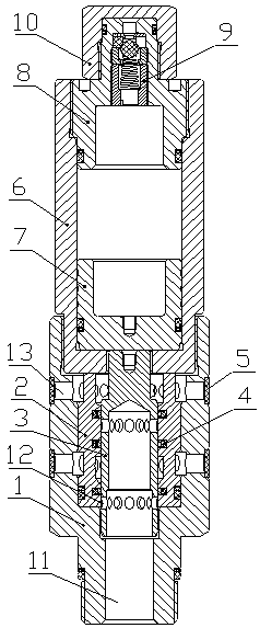
[0035] Such as Figure 1~10 As shown, a safety valve using compressed gas instead of a spring in the present invention includes a valve body 1 and a cylinder 6 affixed to one end of the valve body 1. The cylinder 6 is cylindrical with two ends open. The end of the body 6 away from the valve body 1 has an internal thread, and the internal thread is equipped with a gas nozzle 8, and an O-ring is installed between the gas nozzle 8 and the cylinder body 6, and the gas nozzle 8 is provided with a valve coaxial with the cylinder body 6. The penetrating circular hole, check valve 9 is housed in the circular hole.

[0036] The part of the air nozzle 8 protruding from the cylinder body 6 is covered with a nut 10, the nut 10 is connected to the air nozzle 8 through threads, and the outer ring of the air nozzle 8 is equipped with an ...


PUM


Abstract

The invention relates to a safety valve using compressed gas to replace a spring and a using method of the safety valve. The safety valve comprises a valve body and a cylinder body fixedly connected to one end of the valve body, the end, away from the valve body, of the cylinder body is sealed, the cylinder body is provided with a piston capable of moving in the length direction of the cylinder body, and the piston and an inner cavity of the cylinder body form a closed compressed gas chamber; a valve port is formed in the end, away from the cylinder body, of the valve body, a valve element capable of moving in the length direction of the valve body is installed in the valve body, the end, away from the valve port, of the valve element abuts against the piston, a liquid cavity communicatedwith the valve port is formed in the end, close to the valve port, of the valve element, and multiple through holes are formed in the side wall of the liquid cavity; and a plurality of liquid outletsmatched with the holes are formed in the side wall of the valve body, and the holes are located in the sides, away from the compressed gas chamber, of matched liquid outlets. By means of the safety valve, a traditional mechanical spring structure is replaced with a compressed air mode, and the defects that a mechanical spring is too large in size, difficult to machine, low in precision control andthe like are overcome.

Description

technical field [0001] The invention relates to the technical field of safety valves, in particular to a safety valve using compressed gas instead of a spring and a method for using the same. Background technique [0002] With the gradual development of deep mining in coal mines, more and more occurrences of rock bursts have occurred, and the safety of underground workers and equipment has become a top priority. Due to the small flow rate and slow dynamic response of existing safety valves, they cannot meet the needs of shock-resistant ground pressure hydraulic supports. When the instantaneous impact pressure of the bottom plate is too large, the parts such as columns and top beams are often damaged, which affects the normal underground support. . For this reason, the super-large flow safety valve is an indispensable safety protection hydraulic component in the anti-shock hydraulic support and coal mine safety production. However, the existing large-flow safety valves on t...

Claims


Application Information

Patent Timeline
Patent Type & Authority Applications(China)
IPC IPC(8): F16K17/164F16K31/122E21D15/51
CPCE21D15/512F16K17/164F16K31/122
Inventor 成立良汤京明臧允宾李峰史新刚
Owner 山东赛诺机电设备科技有限公司
Why Eureka
Try Eureka