
Optical cable with new structure and production method thereof

A new structure, optical cable technology, applied in fiber mechanical structure, light guide, optics, etc., can solve the problem of loose tube deformation, achieve the effect of improving performance, improving mechanical stretching and high and low temperature shrinkage performance, and ensuring consistency

Inactive Publication Date: 2020-05-01
NANJING WASIN FUJIKURA OPTICAL COMM LTD
View PDF7 Cites 4 Cited by
  • Summary
  • Abstract
  • Description
  • Claims
  • Application Information

AI Technical Summary

Problems solved by technology

[0007] In order to solve the problems existing in the prior art, the present invention provides a new structural optical cable and a production method that can effectively improve the performance of the optical cable and increase the production efficiency, and at the same time solve the problems of loose tube deformation, repair and tube withdrawal

Method used


Image

  • Optical cable with new structure and production method thereof
  • Optical cable with new structure and production method thereof

Examples


Embodiment 1

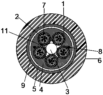
[0032] Such as figure 1 As shown, the present embodiment provides a new structural optical cable, including a loose tube 1, an optical fiber 2, a strength member 3, a PP film 4, a water blocking layer 5 and an outer sheath 6, and the strength member 3 is located at the center of the optical cable , five loose tubes 1 surround the reinforcement 3, the water blocking cable paste 10 is filled between the loose tube 1 and the reinforcement 3, six optical fibers 2 are embedded in the loose tube 1, and the loose tube 1 is filled with The fiber paste 7, the fiber paste 7 wraps the optical fiber 2, and the fiber paste or 7 can seal and waterproof, resist stress and buffer, protect the optical fiber 2, improve the stability of the transmission performance of the optical fiber 2 and the service life of the optical cable.

[0033] In this implementation, the fiber paste can also be replaced by other water-blocking materials.

[0034] The periphery of the five loose tubes 1 is wrapped wi...

Embodiment 2

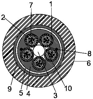
[0050] Such as figure 2 As shown, a new structure optical cable of this embodiment, the structure and production method are basically the same as the embodiment, the difference is that a water blocking yarn 11 is arranged between the loose tube 1 and the reinforcing member 3, and the water blocking yarn 11 is provided with two, and one is vertically arranged, and the other is wrapped around and arranged.

[0051] The water-blocking layer on the periphery of the cable core also uses water-blocking yarn 11 to replace the water-blocking cable paste.


PUM

PropertyMeasurementUnit
Thicknessaaaaaaaaaa

Abstract

The invention discloses an optical cable with a new structure and a production method thereof, and belongs to the technical field of optical cables. The optical cable with the new structure comprisesa reinforcement piece positioned in the centre of the optical cable, a plurality of loose sleeves which surround the periphery of the reinforcement piece and are internally embedded with a plurality of optical fibers, and an outer sheath positioned on the outer layer of the optical cable, and is characterized in that the gap between the plurality of the loose sleeves and the outer sheath is filledwith a PP thin film; and the loose sleeves and the reinforcement piece are tightly combined together through the PP thin film. In a layering stranding process of the production method for the opticalcable with the new structure, a layer of the PP thin film is extruded through a plastic extruding machine; the PP thin film is compressed to wrap the plurality of the loose sleeves by utilizing a compressing mould and fills the gap between adjacent two loose sleeves; after being cooled, the PP thin film is fixed on the periphery of the loose sleeves to form a cable core; and the optical cable with the new structure disclosed by the invention can effectively prevent the sleeves from deforming so as to keep the optical cable structure stable.

Description

technical field [0001] The invention relates to a new-structure optical cable and a production method thereof, belonging to the technical field of optical cable manufacturing. Background technique [0002] The traditional layer-stranded optical cable needs to go through the processes of coloring, plastic coating, layer stranding and sheathing. The layer stranding process uses SZ stranding, and uses polyester yarn to fix the loose tube to form a cable core. However, this process has the following defects: [0003] 1. Because the polyester yarn will shrink when heated, the loose tube will be deformed, which will force the optical fiber and affect the performance and service life of the optical cable. [0004] 2. Because the layer twisted optical cable is affected by the rotation number and tension of the binding machine in the stranding process, the production speed is limited, so the production efficiency is not high. [0005] 3. In order to ensure water seepage, water-block...

Claims


Application Information

Patent Timeline
IPC IPC(8): G02B6/44
CPCG02B6/443G02B6/4434G02B6/4482G02B6/4486G02B6/566G02B6/44384
Inventor 林海龙
Owner NANJING WASIN FUJIKURA OPTICAL COMM LTD
Learn More