Supercharge Your Innovation With Domain-Expert AI Agents!

Long-distance large-view-field iris optical imaging device and long-distance large-view-field iris optical imaging method

An optical imaging system and large field of view technology, applied in the direction of instruments, character and pattern recognition, computer components, etc., can solve problems such as slowness, complicated control, and inability to provide accurate working distances

Inactive Publication Date: 2020-05-01
SUZHOU SIYUAN KEAN INFORMATION TECH
View PDF0 Cites 1 Cited by
  • Summary
  • Abstract
  • Description
  • Claims
  • Application Information

AI Technical Summary

Problems solved by technology

[0002] It is known that the device used for iris imaging has the following defects. The imaging time to obtain an image in a scene with a long working distance and a large working field of view exceeds 1-3s, and the user cannot maintain a consistent relative stillness for such a long time, which is due to the diameter of the iris of the image Requires a large magnification of >200pixel, causing even a very slight movement to exceed the field of view of the iris imaging system, requiring readjustment of the field of view, zoom focus, and lighting
[0003] In addition, traditional distance measurement includes software mapping iris diameter or binocular distance, because due to the difference of more than 20% in the crowd, the error is too large to provide accurate working distance information, which directly affects the overall performance. Similarly, physical measurements such as infrared, ultrasound, and tof In the case of long working distance and large working field of view, the error is too large to provide accurate working distance information. At the same time, known technologies have image quality such as depth of field, image brightness, image relative illuminance, illumination source radiation intensity, and eye iris irradiance. In the case of long working distance and large working field of view, the consistency cannot be guaranteed, and the difference is even several times. The traditional lighting source is adjusted with the inverse square of the working distance, and the radiation intensity of the non-constant light source (for example, the range of 2-3 times the working distance, The field of view changes by 2-3 times, and the radiation intensity changes by 4-9 times), which makes it impossible to meet the requirements of constant field of view and irradiance in a large range at the same time
[0004] Traditionally, a mechanical pan-tilt structure is used to improve the imaging field of view, which leads to complex control, low positioning error accuracy, low stability and reliability, serious problems in power consumption, volume and noise life, and it takes time to start imaging after waiting for the position of the pan-tilt to be adjusted. Very serious Imaging speed is very slow

Method used


Image

  • Long-distance large-view-field iris optical imaging device and long-distance large-view-field iris optical imaging method

Examples


Embodiment 1

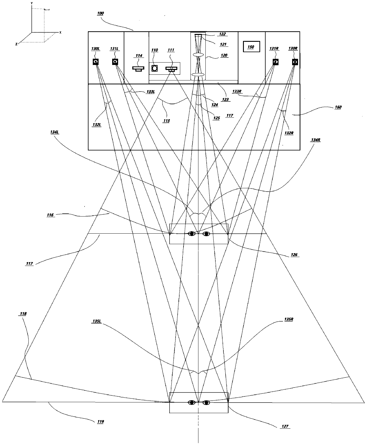
[0130] Such as figure 1 Shown is a schematic diagram of the principle of a long-distance large-field-of-view iris optical imaging device in an embodiment of the present invention. According to this embodiment of the present invention, a long-distance large-field-of-view iris optical imaging device 100 includes: an iris optical tracking system, Iris zoom focusing optical imaging system, LED lighting source radiation system, image display feedback system 160, image processing and drive control system 150.

[0131] The iris optical tracking system includes a 3D depth imaging unit.

[0132] The 3D depth imaging unit can adopt 3D TOF depth imaging or structured light depth imaging (such as 940nm infrared VCSEL light source 110, imaging lens and image imaging sensor 111), or binocular stereo vision imaging (LED lighting source, two groups of Parametrically symmetrical imaging lens and image imaging sensor) provide depth image information.

[0133] The iris zoom and focus optical i...


PUM


Abstract

The invention provides a long-distance large-view-field iris optical imaging device, and the device comprises an iris optical tracking system which comprises a 3D depth imaging unit; an iris zooming and focusing optical imaging system which comprises an optical zooming and focusing lens group and an ultrahigh-resolution image imaging sensor and is used for executing focal length and / or focusing position adjustment of iris imaging according to the 3D physical space point coordinates and physical imaging of the ultrahigh-resolution image imaging sensor; an LED illumination light source radiationsystem which comprises a radiation intensity solid angle and / or a radiation intensity direction angle, and is used for executing combined control in response to the matching relationship between thefield angles of the iris zoom focusing optical imaging system corresponding to different working radiuses / distances according to the coordinates of the 3D physical space point; and image processing and driving control which is carried out to realize driving and feedback control among the system units. The constancy of the view field angle and the radiation illuminance in a large range is realizedat the same time.

Description

technical field [0001] The invention relates to the technical field of optical imaging, in particular to a device and method for long-distance and large-field iris optical imaging. Background technique [0002] It is known that the device used for iris imaging has the following defects. The imaging time to obtain an image in a scene with a long working distance and a large working field of view exceeds 1-3s, and the user cannot maintain a consistent relative stillness for such a long time, which is due to the diameter of the iris of the image A large magnification requirement of >200pixel is required, resulting in that even a very slight movement can cause the field of view of the iris imaging system to be readjusted, zoom focus, and illumination. [0003] In addition, traditional distance measurement includes software mapping of iris diameter or binocular distance, because due to the difference of more than 20% in the population, the error is too large to provide accurat...

Claims


Application Information

Patent Timeline
IPC IPC(8): G06K9/00
CPCG06V40/18
Inventor 倪蔚民
Owner SUZHOU SIYUAN KEAN INFORMATION TECH
Features
  • R&D
  • Intellectual Property
  • Life Sciences
  • Materials
  • Tech Scout
  • Unparalleled Data Quality
  • Higher Quality Content
  • 60% Fewer Hallucinations
Learn More