Plastic composite pipe extruding machine and machining method of plastic composite pipe
A composite pipe and extruder technology, which is applied in the field of plastic composite pipe extruder and plastic composite pipe processing, can solve the problems of inconvenient discharge and achieve the effect of convenient discharge and prevention of clogging
- Summary
- Abstract
- Description
- Claims
- Application Information
AI Technical Summary
Problems solved by technology
Method used
Image

Examples
specific Embodiment approach 1
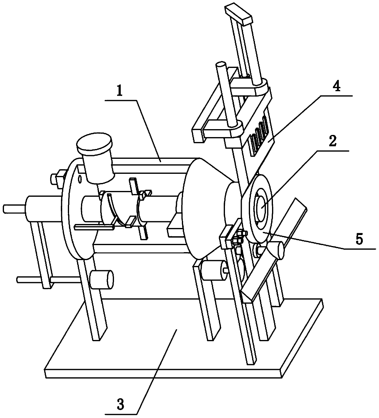
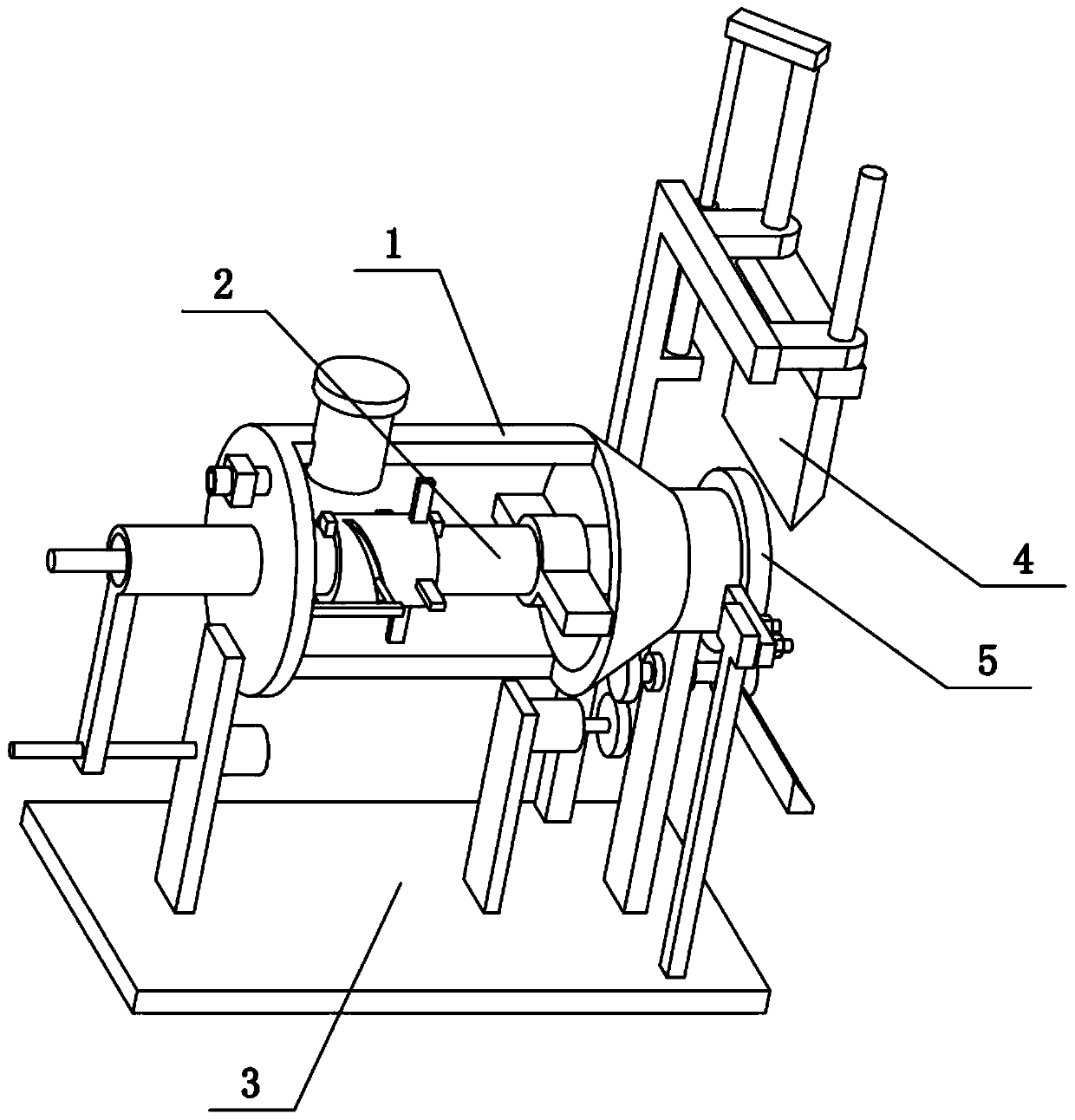
[0036] Combine below Figure 1-9 To illustrate this embodiment, the present invention relates to the field of plastic composite pipe manufacturing, more specifically, a plastic composite pipe extruder, including an extrusion barrel 1, an extrusion port 101, a rear cover 104, a fixing ring 108, and a connecting block 109 , hollow column 2 and heating pipe 204, the present invention is convenient to discharge the residual plastic at the extrusion outlet position on the extruder, and prevents the extrusion outlet position from being blocked next time.
[0037]The left side of the extrusion cylinder 1 is provided with a rear cover 104, the right side of the extrusion cylinder 1 is conical, and the right side of the extrusion cylinder 1 is provided with an extrusion port 101, and the inside of the extrusion cylinder 1 is connected by two The block 109 is fixedly connected with a fixed ring 108, and the fixed ring 108 is coaxially arranged with the extruding cylinder 1. The hollow c...
specific Embodiment approach 2
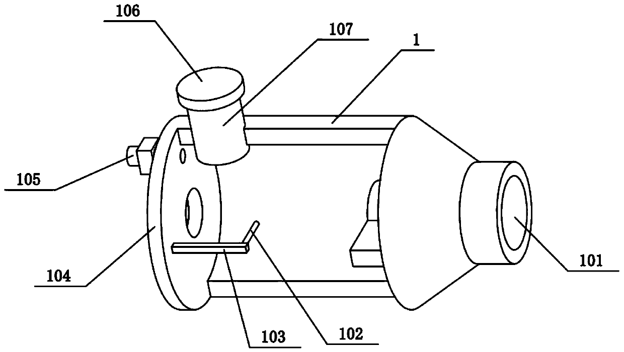
[0039] Combine below Figure 1-9 Illustrate the present embodiment, described plastic composite pipe extruder also comprises air inlet pipe 105, feed pipe cover 106 and feed pipe 107, is provided with air inlet pipe 105 on rear cover 104, is provided with valve on air inlet pipe 105, extrudes A feeding tube 107 is arranged on the left upper end of the cylinder 1, and the upper part of the feeding tube 107 is threadedly connected with a feeding tube cover 106. The air inlet pipe 105 is used to pressurize the air into the extrusion barrel 1 , so that the heated plastic can be extruded from the annular gap formed between the hollow column 2 and the extrusion port 101 . When opening the feed pipe cover 106, the plastic to be melted can be added into the extruding barrel 1 through the feed pipe 107, and then the feed pipe cover 106 is closed during repressurization.
specific Embodiment approach 3
[0041] Combine below Figure 1-9 To illustrate this embodiment, the plastic composite pipe extruder also includes a fixed cylinder 102, a connecting column 103, a rotating cylinder 201, a spiral groove 202, a stopper 205 and an agitating rod 206, and the middle part of the hollow column 2 is connected to the rotating cylinder 201 , the rotating drum 201 is provided with a spiral groove 202, and the rotating drum 201 is provided with a plurality of agitating rods 206 evenly distributed in a ring shape. Between them, the right side of the rear cover 104 is fixedly connected with a connecting column 103 , and the connecting column 103 is fixedly connected with a fixed cylinder 102 , and the fixed cylinder 102 is inserted into the spiral groove 202 . When the hollow column 2 slides left and right, the rotating cylinder 201 moves left and right relative to the fixed cylinder 102, and then the fixed cylinder 102 slides on the spiral groove 202, driving the rotating cylinder 201 to r...
PUM
 Abstract
Description
Claims
Application Information
 - Generate Ideas
- Intellectual Property
- Life Sciences
- Materials
- Tech Scout
- Unparalleled Data Quality
- Higher Quality Content
- 60% Fewer Hallucinations
Browse by: Latest US Patents, China's latest patents, Technical Efficacy Thesaurus, Application Domain, Technology Topic, Popular Technical Reports.
© 2025 PatSnap. All rights reserved.Legal|Privacy policy|Modern Slavery Act Transparency Statement|Sitemap|About US| Contact US: help@patsnap.com