
Heating type conveying mechanism for glass bottles

A conveying mechanism and heating technology, which is applied in the field of glass bottle heating conveying mechanism, can solve the problems of large environmental temperature difference of glass bottles, etc., and achieve the effects of strong heat storage capacity, improved stability, and reduced chance of bursting

Active Publication Date: 2020-05-05
重庆华彬伟玻璃有限公司
View PDF11 Cites 1 Cited by
  • Summary
  • Abstract
  • Description
  • Claims
  • Application Information

AI Technical Summary

Problems solved by technology

[0004] The present invention intends to provide a glass bottle heating conveying mechanism to solve the problem of large temperature difference between the glass bottle and the environment during the glass bottle conveying process

Method used


Image

  • Heating type conveying mechanism for glass bottles
  • Heating type conveying mechanism for glass bottles
  • Heating type conveying mechanism for glass bottles

Examples


Embodiment 1

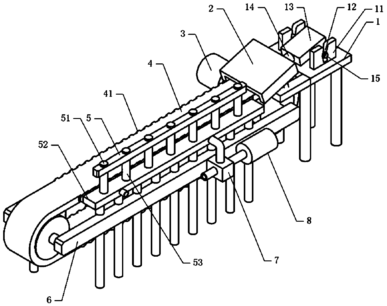
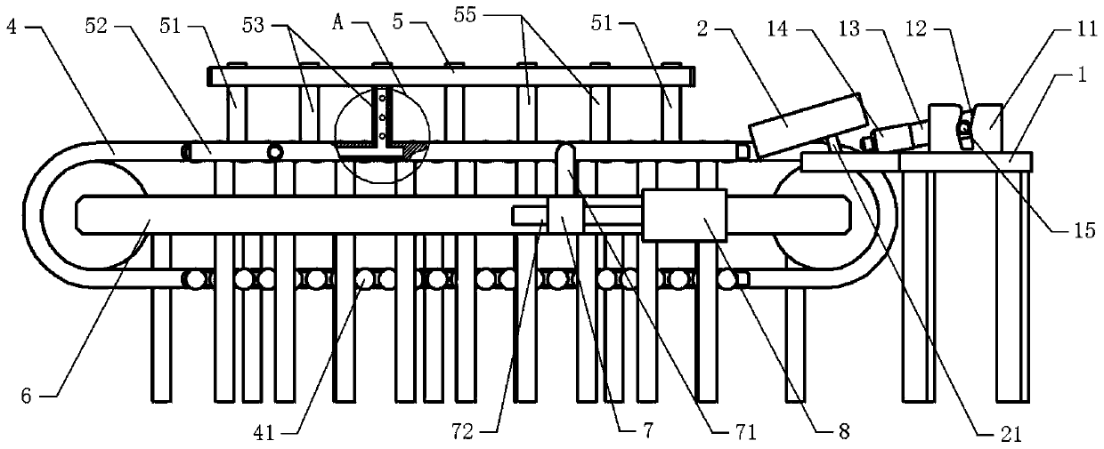
[0041] Basic as attached figure 1 And attached figure 2 As shown, a glass bottle heating conveying mechanism includes a frame 6 and a conveyor belt installed on the frame 6. In this embodiment, the belt 4 of the conveyor belt is made of aluminum alloy, and the frame 6 is fixed and installed by fastening bolts. There is a driving part. In this embodiment, the driving part is a single-phase motor 3, and the output shaft of the single-phase motor 3 is welded coaxially with the transmission shaft of the conveyor belt. as attached Figure 4 , attached Figure 5 And attached Figure 6 As shown, a heat conduction shaft 41 is welded and fixed on the belt 4. The heat conduction shaft 41 is made of a metal material. A heat storage tank 43 is opened on the heat conduction shaft 41. A heat storage sheet 42 made of a ceramic material is installed in the heat storage tank 43. .

[0042] as attached figure 2 As shown, the right end of the conveyor belt is provided with a heating plat...

Embodiment 2

[0051] The difference between embodiment two and embodiment one is that, as attached Figure 7 And attached Figure 8 As shown, two partitions 61 are fixed on the support plate 52 by fastening bolts, and a medium temperature chamber 522 between the hot air chamber and the cold air chamber is formed between the partitions 61, and air holes 62 are opened on the partitions 61, and the medium temperature chamber 522 respectively communicates with the hot air cavity and the cold air cavity through the air hole 62 . The support plate 52 is welded with a number of medium-temperature tubes 57 vertically slidingly connected to the support plate 52. A cavity is opened in the medium-temperature tube 57. A medium-temperature hole 58 facing the conveyor belt is opened on the medium-temperature tube 57. A spiral channel is opened in the medium-temperature tube 57. 59. The spiral channel 59 communicates with the medium temperature cavity 522 and the cavity.

[0052] The specific implementa...


PUM


Abstract

The invention relates to the technical field of glass production, and discloses a heating type conveying mechanism for glass bottles. The heating type conveying mechanism for the glass bottles comprises a conveyer belt driven by a driving part, and heat conduction shafts protruding out of the conveyer belt is installed on the conveyer belt; one end of the conveyer belt is provided with a heating platform and a heating box located above the conveyer belt, and a telescopic shaft fixed to the heating platform is fixedly connected to the heating box; adjusting plates are fixedly installed on the two sides of the heating platform, a fired heater facing the conveyer belt is installed between the adjusting plates, and the fired heater is fixedly provided with an adjusting shaft fixedly matched with adjusting grooves; and the heat conduction shafts are provided with heat accumulation grooves, and heat accumulation sheets are installed in the heat accumulation grooves. According to the heatingtype conveying mechanism for the glass bottles, the structure is simple, heat preservation is conducted on the glass bottles when the glass bottles are conveyed, and the condition that the glass bottles are exploded due to the fact that the temperature difference is too large is avoided.

Description

technical field [0001] The invention relates to the technical field of glass production, in particular to a glass bottle heating conveying mechanism. Background technique [0002] Glass bottles are traditional beverage packaging containers in my country. With many kinds of packaging materials pouring into the market, glass containers still occupy an important position in beverage packaging. [0003] After the glass bottle is formed, it needs to be annealed. The annealed glass bottle is conveyed by the conveyor belt. However, the annealed glass bottle still has a higher temperature, and the temperature of the workshop environment is lower than that of the glass bottle, and the temperature difference is greater than 70°C. As a result, the temperature difference that the glass bottle is subjected to is relatively large, which finally causes the glass bottle to burst during the transmission process, thus resulting in a low yield of the glass bottle. In order to overcome the abo...

Claims


Application Information

Patent Timeline
IPC IPC(8): B65G69/20
CPCB65G69/20
Inventor 上官石林程虎
Owner 重庆华彬伟玻璃有限公司
Learn More