Temporary support structure for foundation pit construction and temporary support construction method

A temporary support and foundation pit technology, which is applied in basic structure engineering, excavation, construction, etc., can solve the problems of poor integrity, poor aesthetics, and damage of the support structure, and achieve increased soil retaining effect, neat and beautiful layout, and increased The effect of supporting the effect

Active Publication Date: 2021-05-18
顺康基础建设有限公司
View PDF6 Cites 1 Cited by
  • Summary
  • Abstract
  • Description
  • Claims
  • Application Information

AI Technical Summary

Problems solved by technology

[0003] The problems existing in the construction of the existing temporary retaining wall are as follows: 1. Most of the existing piles are wooden piles, and the wooden piles will be damaged to a certain extent after use, which makes the piles unable to be recycled, and the piles cannot be recycled. The angle of the pile cannot be limited when the column is inserted, resulting in the inability of the retaining plate to fit on the inner side of the pile, resulting in poor support effect of the support structure;
[0004] 2. The piles are generally connected by steel wire binding. This connection method makes the integrity and aesthetics of the support structure poor

Method used


Image

  • Temporary support structure for foundation pit construction and temporary support construction method
  • Temporary support structure for foundation pit construction and temporary support construction method
  • Temporary support structure for foundation pit construction and temporary support construction method

Examples


Embodiment Construction

[0036] The embodiments of the present invention will be described in detail below with reference to the accompanying drawings, but the present invention can be implemented in many different ways defined and covered by the claims.

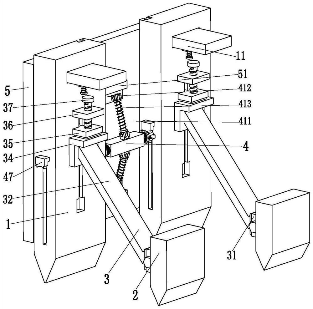
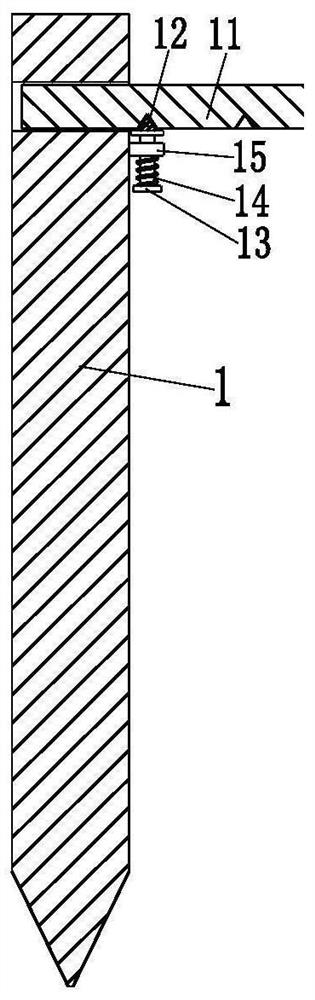
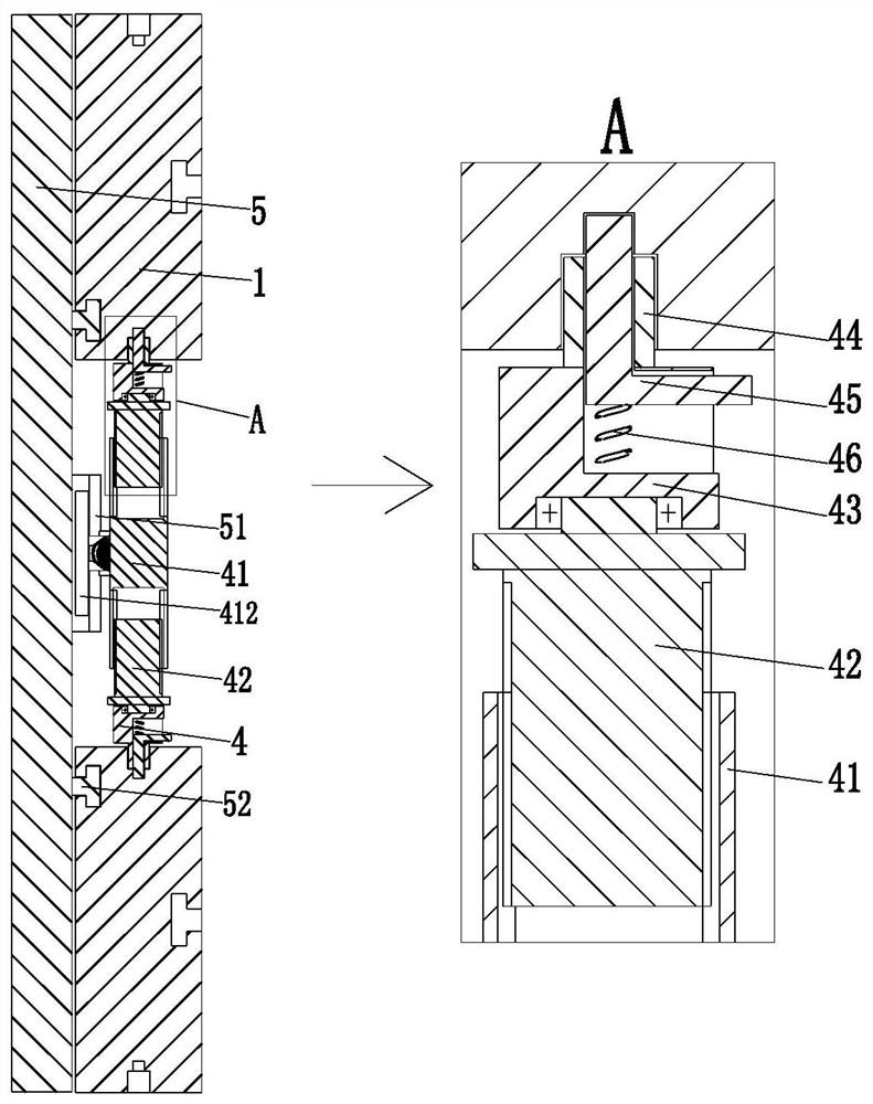
[0037] Such as Figure 1 to Figure 4 As shown, a temporary support structure for foundation pit construction, including piles 1, inclined piles 2, inclined support mechanism 3, limit mechanism 4, soil retaining plate 5, the piles 1 are evenly distributed from front to back , the lower end of the pile 1 is a pointed structure, a T-shaped groove is arranged on the right side of the middle part of the pile 1, a square gap is arranged at the lower end of the T-shaped groove, and a square chute is arranged on the front and rear sides of the pile 1 , a square hole is arranged on the inner wall of the upper end of the square chute, and a diagonal pile 2 is distributed on the right side of each pile 1, the length of the diagonal pile 2 is less than the leng...


PUM


Abstract

The invention relates to a temporary support structure for foundation pit construction and a temporary support construction method, including piles, inclined piles, inclined support mechanisms, limit mechanisms, and soil retaining boards. The piles are uniformly distributed from front to back , a square chute is arranged on the front and rear sides of the pile, a square hole is arranged on the inner wall of the upper end of the square chute, and an obliquely supported pile is distributed on the right side of each pile, between the pile and the obliquely supported pile An oblique support mechanism is connected, a limit mechanism is connected between the inner surfaces of two adjacent piles, and a soil retaining plate is distributed on the left side of each limit mechanism. The present invention can solve the problems existing in the construction of the existing temporary retaining wall: most of the existing piles use wooden piles, and the wooden piles cannot be recycled, and the angle of the piles cannot be limited when the piles are inserted. As a result, the soil retaining board cannot be fitted on the inner side of the pile, resulting in problems such as poor support effect of the support structure.

Description

technical field [0001] The invention relates to the field of building construction, in particular to a temporary support structure for foundation pit construction and a temporary support construction method. Background technique [0002] For foundation pits excavated on slopes, when the width of slopes in some areas is not enough, simple support methods such as temporary retaining wall support can be used for foundation construction. During construction of temporary retaining walls, piles need to be laid along the edge of the foundation pit first. , support the earth retaining board inside the column pile and use the diagonal brace for side support. After the temporary retaining wall is set up, the inner side of the earth retaining board will be filled with soil. The temporary retaining wall is mainly suitable for large foundation pits with small depth. [0003] The problems existing in the construction of the existing temporary retaining wall are as follows: 1. Most of the ...

Claims


Application Information

Patent Timeline
Patent Type & Authority Patents(China)
IPC IPC(8): E02D17/04
CPCE02D17/04
Inventor 龚大娇
Owner 顺康基础建设有限公司
Why Eureka
Try Eureka