Drill pipe deflection correcting and clamping device for geotechnical engineering

A clamping device, geotechnical engineering technology, applied in drill pipe, earthwork drilling, support device, etc., can solve the problems of inconvenient installation of drill pipe, inconvenient operation, inability to adjust the inclination angle of drill pipe and position of drilling point, etc. The effect of headspace, easy installation and removal

Active Publication Date: 2021-06-01
ZUNYI NORMAL COLLEGE
View PDF5 Cites 0 Cited by
  • Summary
  • Abstract
  • Description
  • Claims
  • Application Information

AI Technical Summary

Problems solved by technology

The existing drill pipe correction device only inserts the drill pipe into the limit ring or the guide sleeve, and corrects the drill pipe through the limit ring or the guide sleeve, but when the drill pipe is loaded into the limit ring or the guide sleeve In the interior, due to manual installation factors, there will still be a slight deviation between the drill pipe and the ground or the drill bit of the drill pipe will not be strictly aligned with the drilling point
At the same time, the traditional drill pipe correction device uses the drill pipe to be installed from the top, which requires the drill pipe to be raised to a certain height in advance, which is not only inconvenient to operate, but also takes up a lot of space above
Therefore, aiming at the defects of inconvenient installation of the drill pipe, taking up a lot of upper space, and inability to effectively adjust the inclination angle of the drill pipe and the position of the drilling point after the installation of the drill pipe, the present invention discloses a Drill pipe deflection correction and clamping device for soil engineering

Method used


Image

  • Drill pipe deflection correcting and clamping device for geotechnical engineering
  • Drill pipe deflection correcting and clamping device for geotechnical engineering
  • Drill pipe deflection correcting and clamping device for geotechnical engineering

Examples


Embodiment 1

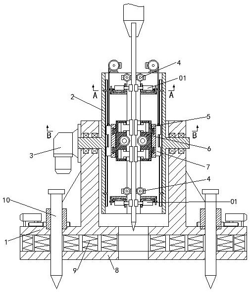
[0037] A kind of geotechnical engineering drill pipe deflection correcting and clamping device of this embodiment, such as figure 1 , Figure 6 , Figure 7 As shown, it includes a base 1, on which a deviation correction base 2 is installed to rotate along the horizontal axis, and a rotating device 3 that drives the deviation correction base 2 to rotate is also arranged on the base 1; the deviation correction base 2 There is a channel for the drill pipe to pass through in the axial direction, and the two ends of the channel are respectively provided with a deviation-correcting clamping device 01, and one side of the deviation-correcting clamping device 01 is coaxially provided with a drill-pipe guiding device 4; the deviation-correcting base On the base 2, a locking frame 5 is slid in the axial direction between the deviation-correcting clamping devices 01 at both ends. The locking frame 5 is provided with a through hole for the drill pipe to pass through. The inside of the th...

Embodiment 2

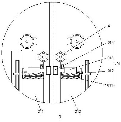
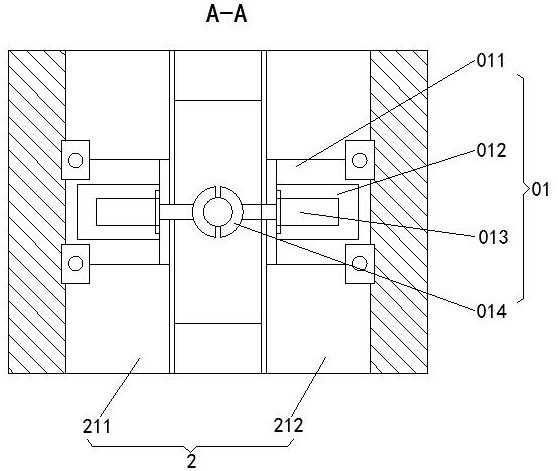
[0045] This embodiment is further optimized on the basis of embodiment 1, such as figure 2 , image 3 , Figure 6 , Figure 7 As shown, the deviation correction clamping device 01 includes a deviation correction installation seat 011, a deviation correction fastening seat 012, a deviation correction oil cylinder 013, and a deviation correction chuck 014. On the side, the deviation correction mounting seat 011 is slidably installed with a deviation correction fastening seat 012 along the direction perpendicular to the axial direction of the deviation correction base 2, and the deviation correction fastening seat 012 is installed with a deviation correction The oil cylinder 013, the end of the push rod of the deviation correction oil cylinder 013 is equipped with a deviation correction chuck 014 for clamping the drill pipe.

[0046] The deviation correction support 2 includes a left deviation correction support 211 and a right deviation correction support 212 symmetrically a...

Embodiment 3

[0053] This embodiment is further optimized on the basis of above-mentioned embodiment 1 or 2, such as Figure 4 and Figure 5 As shown, the drill pipe clamping device 6 includes a clamping ring seat 61, a drill pipe chuck 62, and a clamping piston 63. The clamping ring seat 61 is rotatably arranged in the through hole of the locking frame 5. On the inner ring surface of the clamping ring seat 61, there are at least two piston cavities perpendicular to the axial direction of the drill rod symmetrically about the center of the circle. A clamping piston 63 is slidably arranged in the piston cavity, and the clamping piston 63 separates the piston cavity. It is the first cavity 111 and the second cavity 222, and the first cavity 111 and the second cavity 222 communicate with the outside through hydraulic pipes respectively; one end of the clamping piston 63 extends out of the piston cavity and connects with the One side of the drill chuck 62 is attached.

[0054] The first chamb...


PUM


Abstract

The invention discloses a drilling rod deviation correcting and clamping device for geotechnical engineering, which comprises a base, on which a deviation correcting base is installed to rotate along the direction of a horizontal axis, and a rotating device for driving the deviation correcting base to rotate is also arranged on the base. device; the deviation correction base is axially provided with a passage for the drill pipe to pass through, and the two ends of the passage are respectively provided with a deviation correction clamping device, and one side of the deviation correction clamping device is coaxially provided with a drill pipe guiding device; On the deviation correction base, a locking frame is slid between the deviation correction clamping devices located at both ends in the axial direction. The locking frame is provided with a through hole for the drill pipe to pass through. Drill pipe clamping device, one end of the deviation correction base is also provided with a sliding device that drives the locking frame to slide; the invention has the advantages of convenient disassembly and assembly of the drill pipe, effective saving of upper space, correction of the inclination angle and drilling point of the drill pipe, Effectively ensure that the drill pipe is vertical to the ground, the drill bit of the drill pipe is aligned with the drilling point, and the drilling process is stable.

Description

technical field [0001] The invention belongs to the technical field of geotechnical engineering, and in particular relates to a drill pipe deflection correcting and clamping device for geotechnical engineering. Background technique [0002] The drill pipe is one of the necessary components for drilling in geotechnical engineering. When the drill pipe is used to drill holes on the ground, the position of the drill pipe will move when the drill pipe is manually hoisted and installed. The axis of the rod may not be perpendicular to the ground, and the projection of the drill bit of the drill pipe on the ground is not aligned with the drilling point, which requires a special correction device to adjust the inclination angle of the drill pipe and the position of the drilling point. The existing drill pipe correction device only inserts the drill pipe into the limit ring or the guide sleeve, and corrects the drill pipe through the limit ring or the guide sleeve, but when the drill...

Claims


Application Information

Patent Timeline
Patent Type & Authority Patents(China)
IPC IPC(8): E21B7/10E21B15/04E21B19/24E21B19/10
CPCE21B7/10E21B15/04E21B19/10E21B19/24
Inventor 袁余洋
Owner ZUNYI NORMAL COLLEGE
Why Eureka
Try Eureka