
Displacement control device

A technology of control device and displacement, applied in valve device, pump control, fluid pressure actuating device, etc., can solve the problems of unstable displacement and operation of pressure fluid unit, and achieve the effect of suppressing irregularity

Active Publication Date: 2020-05-05
DANFOSS POWER SOLUTIONS GMBH & CO
View PDF14 Cites 0 Cited by
  • Summary
  • Abstract
  • Description
  • Claims
  • Application Information

AI Technical Summary

Problems solved by technology

All these effects are further transmitted directly or indirectly to the control device, especially to the control spool, resulting in unstable displacement and operation of the pressure fluid unit

Method used


Image

  • Displacement control device
  • Displacement control device
  • Displacement control device

Examples


Embodiment Construction

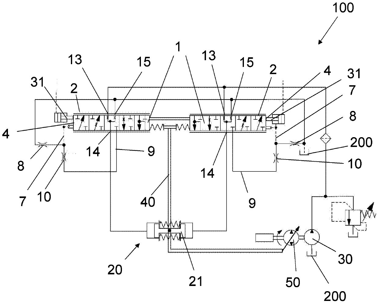
[0030] figure 1 A schematic hydrostatic circuit diagram of a hydrostatic unit 50 with a two-sided displacement control device 100 is shown. The displacement control device 100 shows a symmetrically formed control cylinder 2 in which a symmetrical control spool 1 can move in two directions along the longitudinal direction 3 of the control spool or control cylinder, respectively. Charge pressure from a charge pump 30 can be supplied via two inlets 13 . The servo unit 20 for adjusting the displacement of the hydraulic unit 50 can be arranged via two servo ports 14 on one side with pressurized fluid, wherein the pressurized fluid can be discharged from the corresponding other servo side - depending on the control spool direction of movement. For example, if control spool 1 is at figure 1 Moving to the left on the plane of the control spool 1, the servo port 14 on the left side of the control spool 1 is connected to the left inlet 13. Meanwhile, the servo port 14 on the right s...


PUM


Abstract

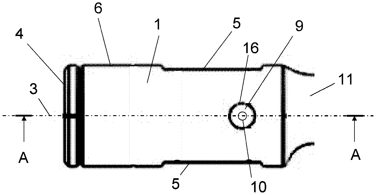
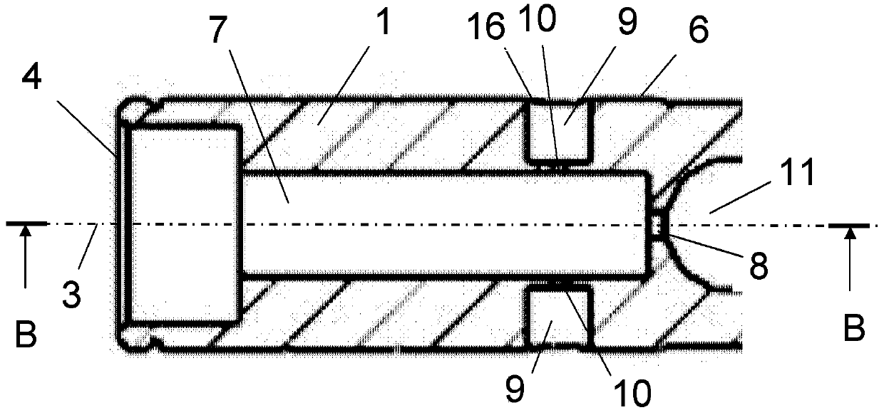
Provided is a displacement control device for providing pressure fluid to a servo unit for adjusting the displacement of a pressure fluid unit, having a control cylinder in which a control spool is mounted shiftable along the longitudinal axis of the control cylinder, an inlet port, a servo port and a discharge port are formed in the control cylinder longitudinally spaced from each other, whereinthe control spool comprising: a basically cylindrical outer surface; a front face on which an actuation force can act for shifting the control spool along the longitudinal axis; a discharge area opposite to the front face; a longitudinal bore inside the control spool, wherein one end of the longitudinal bore opens towards the front face and the other end is connected via a backpressure orifice with the discharge area; a control recess provided lengthwise in the outer surface; a radial bore which connects via a flow limiting orifice the longitudinal bore with the outer surface, wherein the opening of the radial bore at the outer surface is located in circumferential direction beside the control recess, such that the opening of radial bore overlaps with the servo port in an actuated positionof the control spool, in which the control recess connects the inlet port with the servo port.

Description

technical field [0001] The invention relates to a displacement control device of a pressure fluid unit, which is used for providing pressurized fluid to a servo unit, and the servo unit is used for adjusting the displacement of the pressure fluid unit. The invention relates, for example, to hydrostatic propulsion units, but is not limited to such units. The invention relates in particular to an improved displacement control arrangement which provides better control and monitoring of the displacement of a pressure fluid unit. Furthermore, in particular, the present invention relates to an improved control spool for such a displacement control device. [0002] For reasons of simplification, the invention has only been described using a hydrostatic propulsion unit as an example, but the invention can also be applied to pneumatic units or the like. Background technique [0003] Especially under the control of a hydrostatic propulsion unit, the control force used to regulate th...

Claims


Application Information

Patent Timeline
IPC IPC(8): F15B13/02F16K11/07
CPCF15B13/02F16K11/0716F15B13/0402F15B13/0407F15B2211/20553F04B49/002F15B15/204F16K11/0712
Inventor 莱因哈特·汤姆斯马丁·伍斯特菲尔德苏梅尔·施尼维萨姆西
Owner DANFOSS POWER SOLUTIONS GMBH & CO
Learn More