Flow rate detection device, flow rate control system, and flow rate detection method
A flow detection device and a technology of flow value, which are applied in the direction of flow control using electrical devices, flow control, and detection of fluid flow by measuring differential pressure. The effect of improving detection efficiency
- Summary
- Abstract
- Description
- Claims
- Application Information
AI Technical Summary
Problems solved by technology
Method used
Image
Examples
Embodiment 1
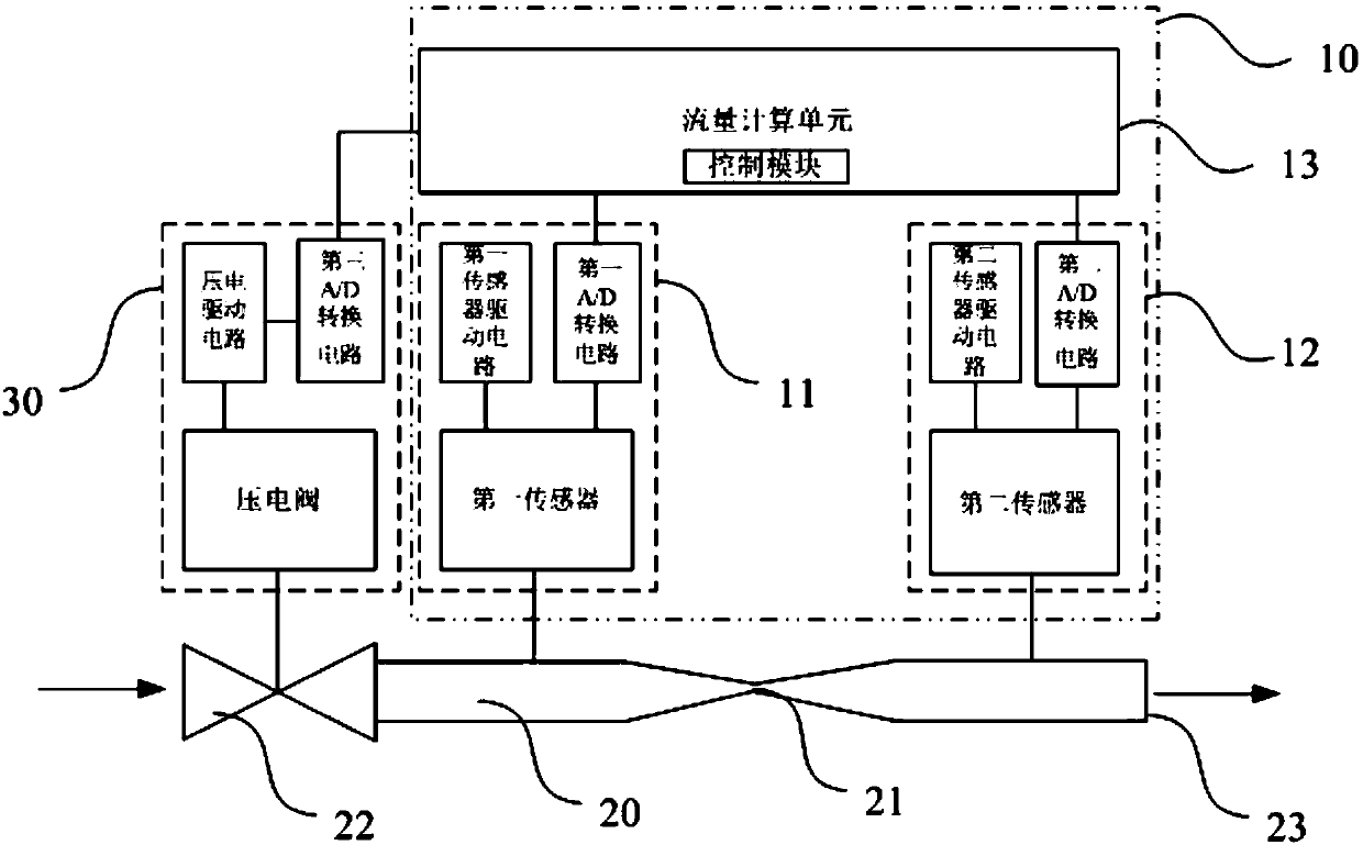
[0037] The present invention provides a flow detection device 10, the flow detection device 10 can be a gas mass flow detection device, a gas volume flow detection device, or other suitable gas flow detection devices, in this embodiment the gas mass flow detection device As an example to describe.
[0038] Such as figure 1 As shown, the flow detection device 10 of this embodiment is used to detect the flow rate in the gas channel 20, the gas channel 20 includes connected upstream channels and downstream channels, the connection of the upstream channel and the downstream channel forms a throat 21, and the throat The cross-sectional area of the mouth 21 is smaller than the cross-sectional area of any one of the upstream passage and the downstream passage, and the flow detection device 10 includes:
[0039] The first pressure testing unit 11 is used to measure the first pressure value of the upstream channel;
[0040] The second pressure testing unit 12 is used to measure t...
Embodiment 2
[0056] Such as figure 1 As shown, this embodiment provides a flow control system, including:
[0057] The flow detection device 10 in embodiment 1;
[0058] The gas channel 20 includes an upstream channel and a downstream channel that are connected. The gas flows in from the upstream channel and then flows out through the downstream channel. Wherein, the junction of the upstream channel and the downstream channel forms a throat 21, and the cross-sectional area of the throat 21 is smaller than that of the upstream channel. and the cross-sectional area of either of the downstream channels;
[0059] The valve device 30 is arranged at the gas inlet 22 of the upstream channel, and is used for controlling the gas flow of the gas channel 20 according to the corrected flow value obtained by the flow detection device 10 .
[0060] Wherein, the cross-sectional area of the throat 21 of the gas channel 20 mentioned here can be that the cross-sectional area of the upstream channe...
Embodiment 3
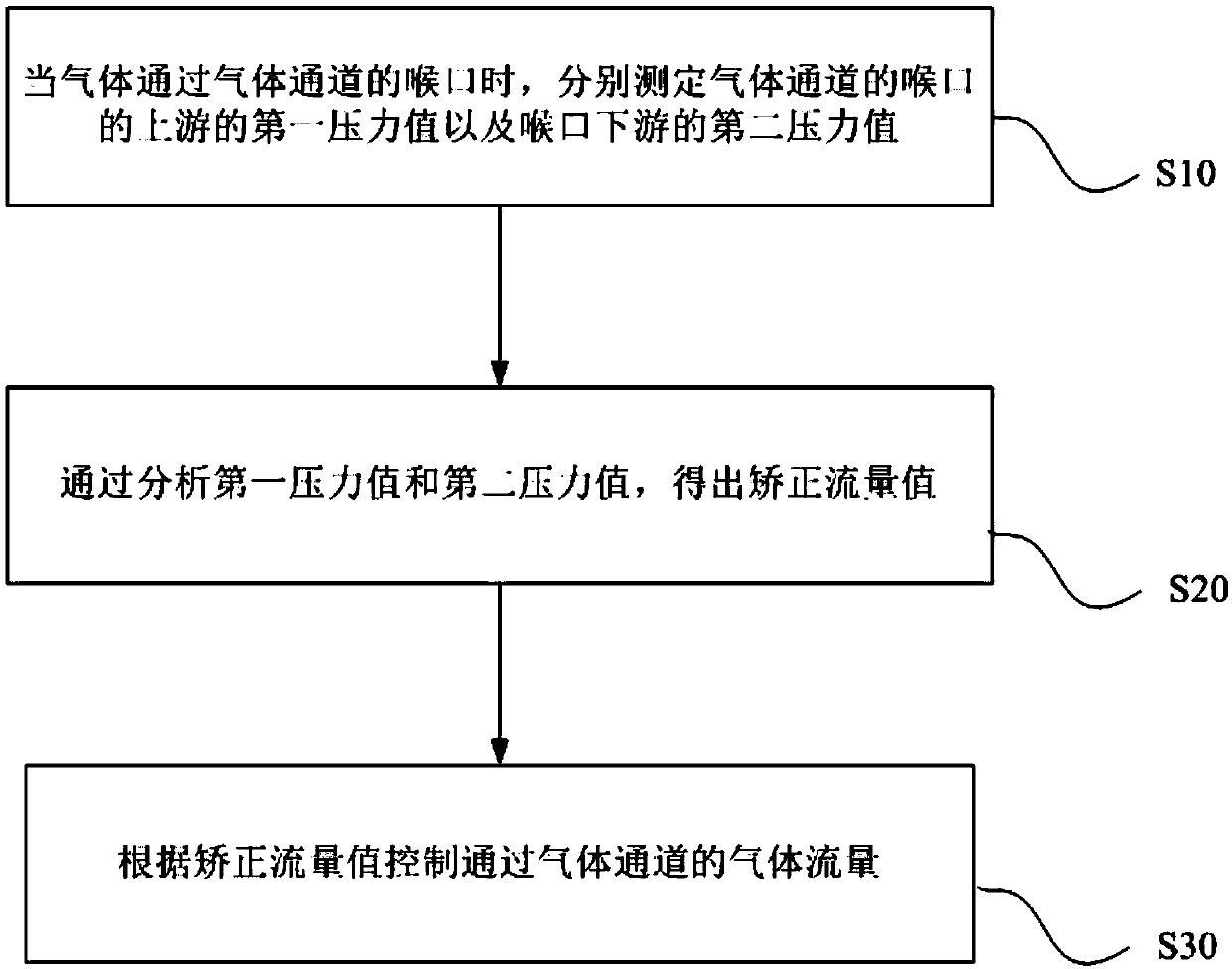
[0067] Such as image 3 As shown, this embodiment provides a detection method for a flow detection device, which may be a method for a gas mass flow detection device, a method for a gas volume flow detection device, or other suitable gas flow detection methods. In this embodiment Take the detection device used for gas mass flow detection device as an example to describe
[0068] The detection method of the flow detection device includes:
[0069] S10, when the gas passes through the throat 21 of the gas channel 20, respectively measure the first pressure value of the upstream channel and the second pressure value of the downstream channel of the gas channel 20.
[0070] Wherein, the gas passage 20 includes an upstream passage and a downstream passage connected, and the junction of the upstream passage and the downstream passage forms a throat 21, and the cross-sectional area of the throat 21 is smaller than that of any one of the upstream passage and the downstream passage....
PUM
 Abstract
Description
Claims
Application Information
 - R&D
- Intellectual Property
- Life Sciences
- Materials
- Tech Scout
- Unparalleled Data Quality
- Higher Quality Content
- 60% Fewer Hallucinations
Browse by: Latest US Patents, China's latest patents, Technical Efficacy Thesaurus, Application Domain, Technology Topic, Popular Technical Reports.
© 2025 PatSnap. All rights reserved.Legal|Privacy policy|Modern Slavery Act Transparency Statement|Sitemap|About US| Contact US: help@patsnap.com


