
A shaft sleeve detection and sorting device and method

A sorting device and shaft sleeve technology, applied in sorting and other directions, can solve the problems of low detection efficiency of shaft sleeves, prone to false detection, missed detection, etc., and achieve the effect of improving detection and sorting efficiency and high detection accuracy

Active Publication Date: 2021-06-29
CHINA THREE GORGES UNIV
View PDF0 Cites 0 Cited by
  • Summary
  • Abstract
  • Description
  • Claims
  • Application Information

AI Technical Summary

Problems solved by technology

[0003] The technical problem to be solved by the present invention is to provide a shaft sleeve detection and sorting device and method, which are used to solve the problems of low efficiency of manual detection of shaft sleeves and prone to false detection or missed detection

Method used


Image

  • A shaft sleeve detection and sorting device and method
  • A shaft sleeve detection and sorting device and method
  • A shaft sleeve detection and sorting device and method

Examples


Embodiment Construction

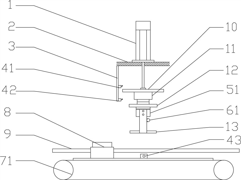
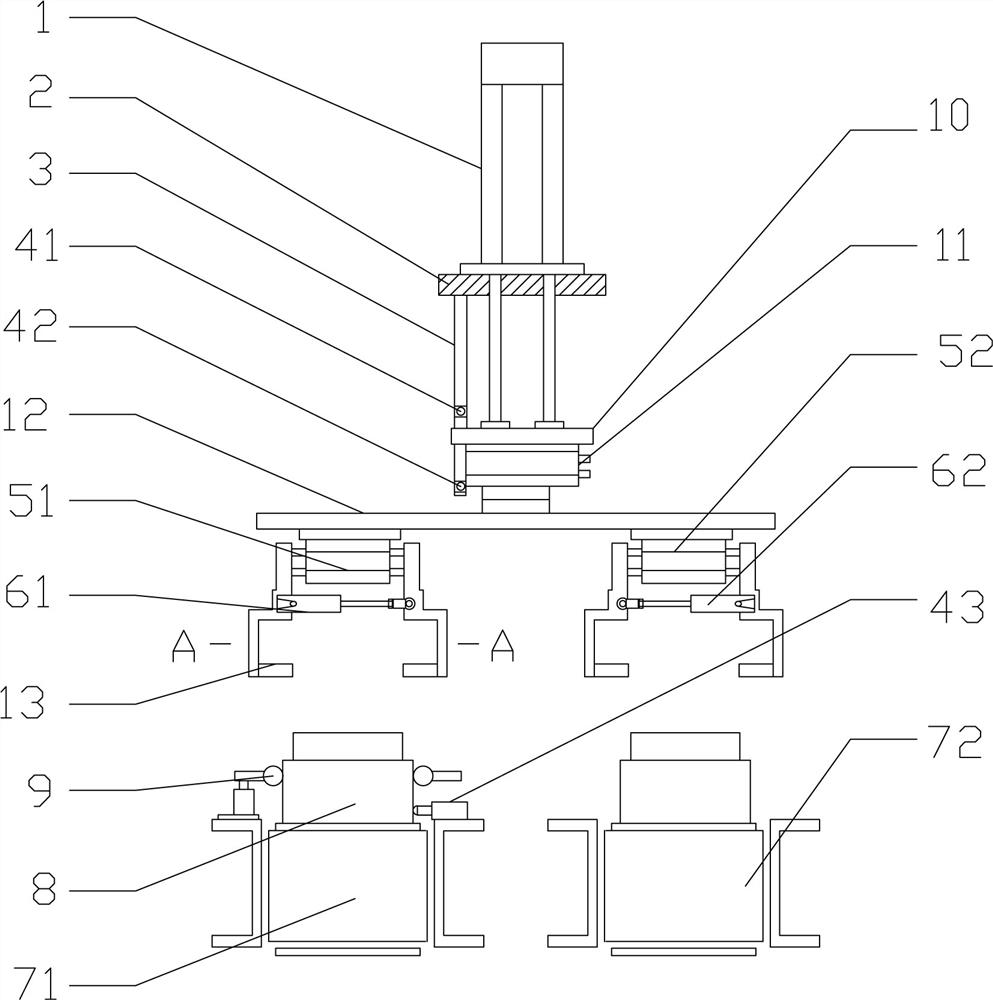
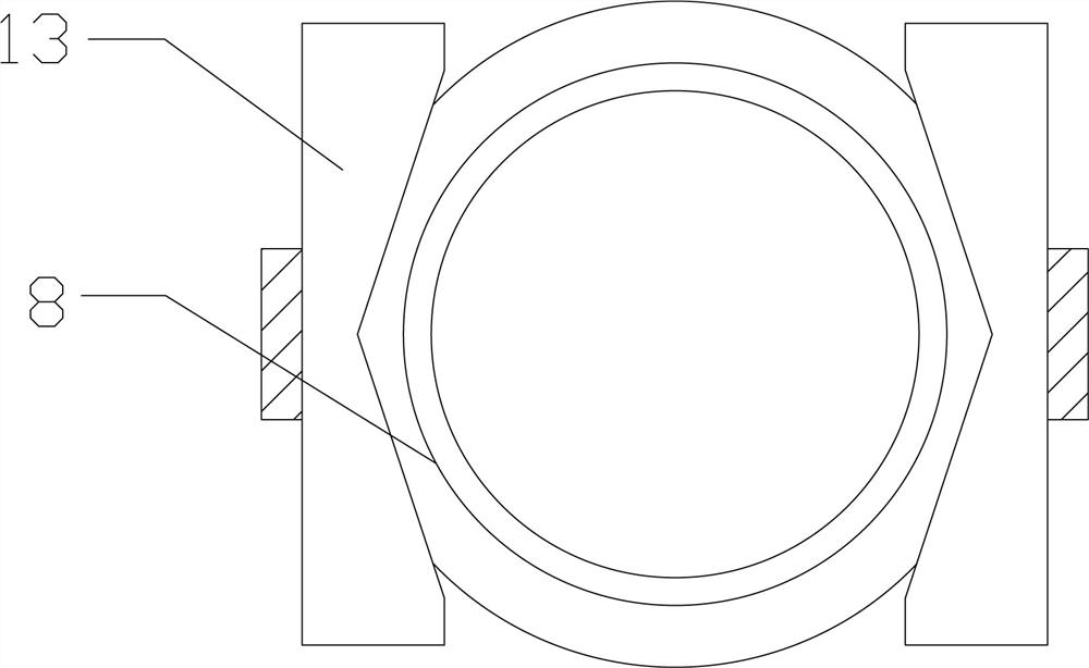
[0015] Such as Figures 1 to 5 As shown, a shaft sleeve detection and sorting device includes a first belt conveyor 71, and the frame of the first belt conveyor 71 is provided with two guide rods 9, and the two guide rods 9 are mounted on the first belt conveyor 71. A channel is separated, and the first belt conveyor 71 carries the bushing 8 through the passage. During the conveying process of the bushing 8 on the first belt conveyor 71, two guide rods 9 are attached to both sides of the bushing 8. A support 2 is provided on one side of the first belt conveyor 71, and a biaxial linear cylinder 1 is installed on the support 2. The lower end of the piston rod of the linear cylinder 1 is connected to the rotary cylinder 11 through the first support plate 10, and the second support plate 12 is connected to the On the rotary end of the rotary cylinder 11, a first pneumatic gripper 51 is installed at one end of the second support plate 12, and splints 13 are respectively fixedly ins...


PUM


Abstract

A shaft sleeve detection and sorting device and method, including a first belt conveyor, two guide rods are arranged on the frame of the first belt conveyor, and a passage is formed between the two guide rods on the first belt conveyor, and the first The belt conveyor carries the bushing through the channel. A bracket is installed on the side of the first belt conveyor. A linear cylinder is installed on the bracket. The lower end of the piston rod of the linear cylinder is connected to the rotary cylinder through the first support plate, and the second support plate Connected to the rotary end of the rotary cylinder, the first pneumatic gripper is installed at one end of the second support plate, splints are fixedly installed on the piston rods at both ends of the first pneumatic gripper, and triangles are provided on the opposite ends of the two splints. gap. The invention is used to solve the problems that manual detection of shaft sleeves is inefficient and prone to false detection or missing detection.

Description

technical field [0001] The invention relates to a shaft sleeve detection and sorting device and method. Background technique [0002] After the shaft sleeve is processed by the CNC lathe, the size of the shaft sleeve needs to be tested. The purpose of the detection method is mainly through manual testing. On the one hand, this detection method is not efficient and affects the production cycle. On the other hand, it is There is visual fatigue in manual detection, which leads to false detection or missed detection. Contents of the invention [0003] The technical problem to be solved by the present invention is to provide a device and method for detecting and sorting shaft sleeves, which are used to solve the problems of low efficiency of manual detection of shaft sleeves and prone to false detection or missed detection. [0004] In order to solve the above problems, the technical solution to be solved in the present invention is: [0005] A shaft sleeve detection and sort...

Claims


Application Information

Patent Timeline
Patent Type & Authority Patents(China)
IPC IPC(8): B07C5/08B07C5/02B07C5/36
CPCB07C5/02B07C5/08B07C5/362
Inventor 喻颖倩聂大林胡品端刘雯婷白雨欣陈乐朋
Owner CHINA THREE GORGES UNIV
Learn More