

Precision shaft butt joint equipment and precision shaft butt joint method
A precision shaft and equipment technology, applied in metal processing equipment, measuring devices, instruments, etc., can solve the problems of poor interchangeability between shafts and shafts, deformed connecting shafts, cumbersome detection, etc.
- Summary
- Abstract
- Description
- Claims
- Application Information
AI Technical Summary
Problems solved by technology
Method used
Image

Examples
Embodiment Construction
[0028] The present invention will be further described in detail below in conjunction with the accompanying drawings and specific embodiments.
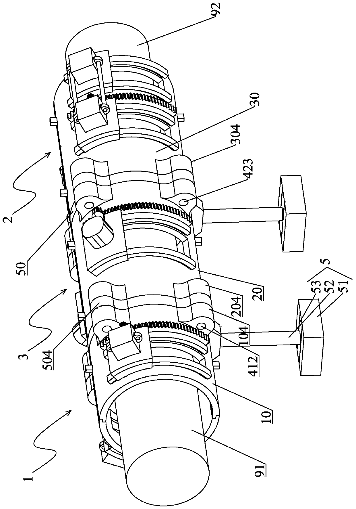
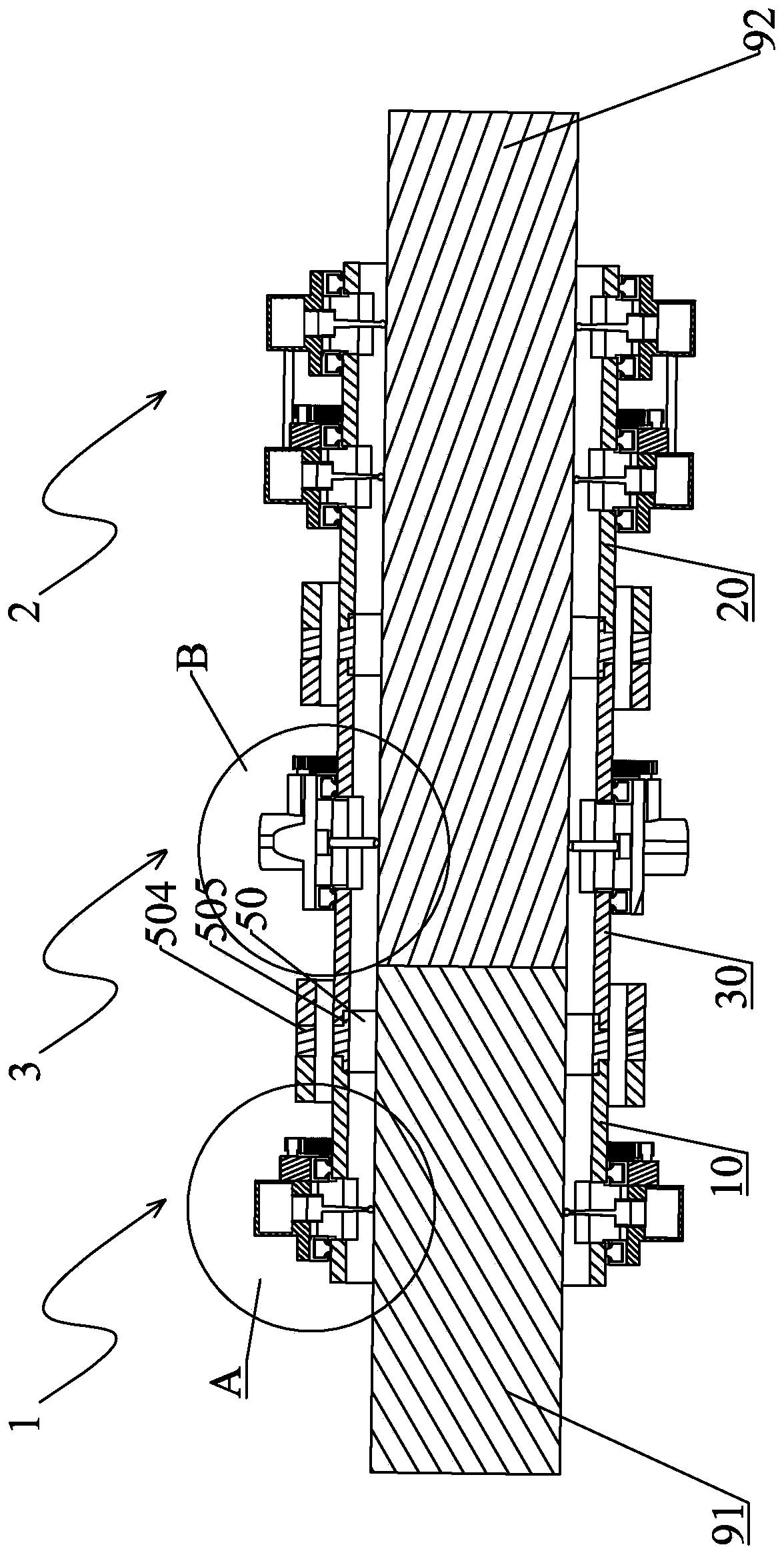
[0029] What the present invention discloses is a kind of precision shaft docking equipment, such as Figure 1-2 As shown, it is a preferred embodiment of the present invention. The precision shaft butt joint equipment includes a straightening part 1 sleeved on the first shaft 91 and a detection part 2 and a correction part 3 sleeved on the second shaft 92. The precision The shaft interfacing device realizes shaft interfacing between the first shaft 91 and the second shaft 92 . In order to realize the precise coaxial docking of the two axes, the alignment part 1, the detection part 2 and the correction part 3 are coaxially distributed, and the correction part 3 is set between the alignment part 1 and the detection part 2, and the three can be mutually The three sections that are fixedly connected may also be integrally formed. In this...
PUM
 Abstract
Description
Claims
Application Information