Cutting tool for busbar heat-shrinkable tube

A technology of heat-shrinkable tubes and busbars, which is applied in metal processing and other directions, can solve the problems of hidden safety hazards and low efficiency of heat-shrinkable tubes for busbars, and achieve the effect of simple and efficient cutting and safe use

Active Publication Date: 2022-05-20
HENAN PINGGAO GENERAL ELECTRIC CO LTD +2
View PDF7 Cites 3 Cited by
  • Summary
  • Abstract
  • Description
  • Claims
  • Application Information

AI Technical Summary

Problems solved by technology

[0004] The purpose of the present invention is to provide a cutting tool for busbar heat-shrinkable tubes, so as to solve the technical problems of manual cutting of busbar heat-shrinkable tubes in the prior art, which has potential safety hazards and low efficiency

Method used


Image

  • Cutting tool for busbar heat-shrinkable tube
  • Cutting tool for busbar heat-shrinkable tube
  • Cutting tool for busbar heat-shrinkable tube

Examples


Embodiment Construction

[0032] Embodiments of the present invention will be further described below in conjunction with the accompanying drawings.

[0033] Specific embodiments of the cutting tool for busbar heat-shrinkable tubes provided by the present invention:

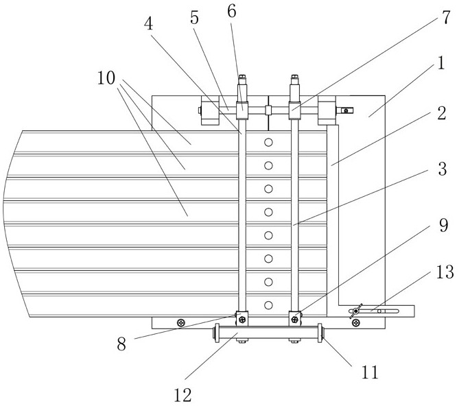
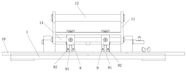
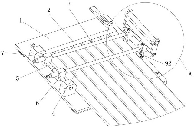
[0034] like Figure 1 to Figure 4 As shown, the busbar heat-shrinkable tube cutting tool includes a base 1, which is used to lay a plurality of busbars 10 horizontally along the front and rear directions. The busbars 10 extend along the left and right directions. Copper row.

[0035] A stop ruler 2 is provided on the base 1 for positioning and cooperating with the end stop of the busbar 10 . The stop ruler 2 is an L-shaped structure including vertical and horizontal sides. The vertical side of the stop ruler 2 is matched with the right end surface of the busbar 10 for blocking and positioning. After the left and right directions are adjusted in place, the bolt passes through the long hole 13 to screw the stopper 2 onto the base 1 .

...


PUM


Abstract

The invention provides a tool for cutting busbar heat-shrinkable tubes, which includes a base for laying a plurality of busbars extending along the left and right directions sequentially along the front and rear directions; The end of the busbar is positioned and matched; the guide piece is set on the base to guide and move along the front and rear directions; the cutting knife is installed on the guide piece, and the heat shrinkable tube on the busbar is moved along with the front and back movement of the guide piece. Cutting, when cutting the heat-shrinkable tube of the busbar, place multiple busbars side by side on the base along the front and rear directions, make the ends of the busbars and the stopper stop and position each other, and then move the guide rod along the front and rear directions, so that The cutting knife installed on the guide bar starts to cut the heat shrinkable tube of the busbar, which makes the cutting of the heat shrinkable tube of the busbar more simple and efficient, and the cutting knife moves along with the guide bar to ensure the safety of the operator.

Description

technical field [0001] The invention relates to a tool for cutting heat-shrinkable tubes of busbars. Background technique [0002] Multiple busbars are used in electrical switch products such as distribution boxes and cable distribution boxes, and heat shrinkable tubes are wrapped around the busbars to insulate the busbars. At the overlapping joints electrically connected with other wires and wires, a part of the heat shrinkable tube needs to be cut off. [0003] In the prior art, such as a Chinese utility model patent with the authorized announcement number CN207710899U discloses a heat-shrinkable tube cutting and positioning device, which includes a positioning sleeve, a measuring ruler and a locking bolt arranged on the positioning sleeve. When in use, Pass the busbar covered with heat-shrinkable tube through the positioning sleeve, measure the length of the exposed part of the busbar with a measuring ruler, lock and fix the positioning sleeve on the busbar through the l...

Claims


Application Information

Patent Timeline
Patent Type & Authority Patents(China)
IPC IPC(8): B26D1/11B26D5/10B26D7/26B26D7/01
CPCB26D1/11B26D5/10B26D7/2628B26D7/2614B26D7/01B26D7/0006
Inventor 谢景会陈东风宫原捷陈艳彪张二勇孙琪阎启栋娄文亮潘乙郭佩淇
Owner HENAN PINGGAO GENERAL ELECTRIC CO LTD
Why Eureka
Try Eureka