A processing method and device for a shape-controllable 3D helical micro-antenna

A processing device, 3D technology, applied in the direction of coating, household appliances, household components, etc., can solve the problems of limited processing size, low processing efficiency and high cost of spiral micro-conductor, achieve unlimited processing size, easy device maintenance, The effect of saving production time

Active Publication Date: 2020-08-11
GUANGDONG UNIV OF TECH
View PDF2 Cites 0 Cited by
  • Summary
  • Abstract
  • Description
  • Claims
  • Application Information

AI Technical Summary

Problems solved by technology

[0004] In view of the above defects, the object of the present invention is to propose a shape-controllable 3D helical micro-antenna processing device to solve the problems of low processing efficiency, high cost, complex structure and difficult operation of the existing helical micro-antenna processing device
[0005] Another object of the present invention is to propose a shape-controllable 3D helical micro-antenna processing method, which solves the problem that the disposable support structure is used repeatedly in the existing three-dimensional structure printing, the processing size of the helical micro-conductor is limited, and the generated micro-conductor is less Difficult problem with helical structure control

Method used


Image

  • A processing method and device for a shape-controllable 3D helical micro-antenna
  • A processing method and device for a shape-controllable 3D helical micro-antenna
  • A processing method and device for a shape-controllable 3D helical micro-antenna

Examples


Embodiment 1

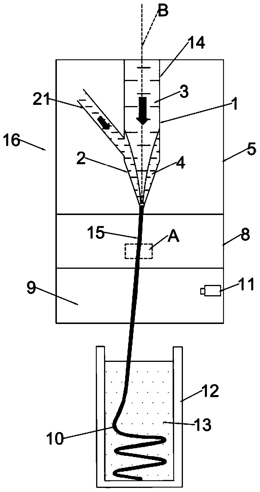
[0087] The outer tube 2 has a constriction diameter of 50 μm, and the inline tube 1 has a constriction diameter of 10 μm;

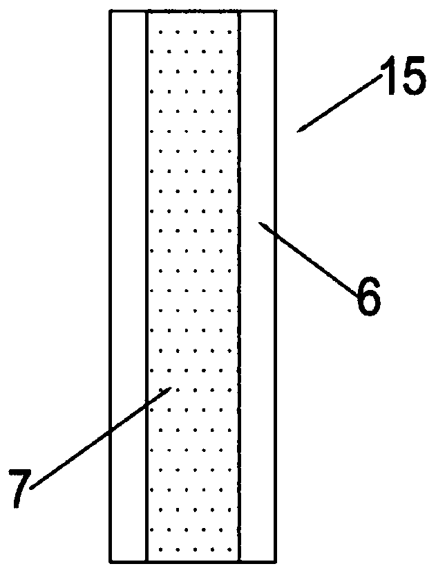
[0088] Apply a pressure of 54psi to the conductive paste, and apply a pressure of 55psi to the functional hydrogel, so that the conductive paste and the functional hydrogel are simultaneously extruded at a speed of 0.2mm / s to form a microwire 15; the wavelength is 405nm, and the power is 10mW of ultraviolet light cures the micro wire 15;

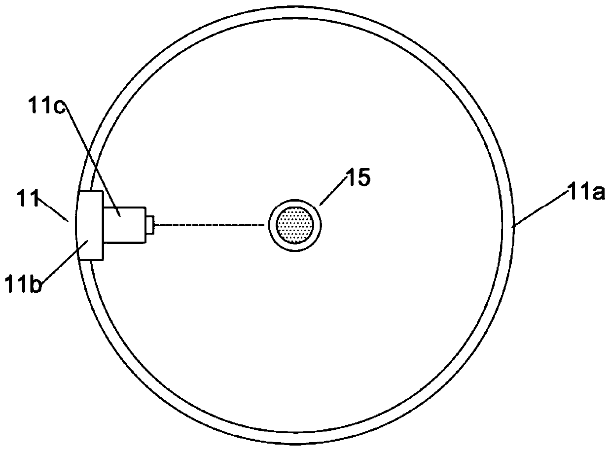
[0089] The rotating light source 11 aligns the micro wire 15 with a continuous wave laser with a power of 500mW, and rotates counterclockwise at a speed of 1rps. Such as Figure 4 As shown, an equal-diameter 3D helical micro-antenna 10 with a diameter of 5 mm and a pitch of 1 mm is shown.

Embodiment 2

[0091] The outer tube 2 has a constriction diameter of 50 μm, and the inline tube 1 has a constriction diameter of 10 μm;

[0092] Apply a pressure of 54psi to the conductive paste, and apply a pressure of 55psi to the functional hydrogel, so that the conductive paste and the functional hydrogel are simultaneously extruded at a speed of 0.2mm / s to form a microwire 15; the wavelength is 405nm, and the power is 10mW of ultraviolet light cures the micro wire 15;

[0093] The rotating light source 11 uses a continuous wave laser with a power of 500mW to align the micro-wire 15 with an acceleration of 0.1rps per second to rotate counterclockwise at a speed of 1rps and continue processing for 60s. The micro-wire 15 has a viscosity of 3.0k·mPa·s supporting solution 13 for centrifugal movement, forming such as Figure 5 As shown, a variable-diameter 3D helical micro-antenna 10 with a maximum diameter of 5 mm, a minimum diameter of 0.5 mm, and a pitch of 1.5 mm.


PUM

PropertyMeasurementUnit
wavelengthaaaaaaaaaa

Abstract

The invention discloses a processing method and device for a shape-controllable three-dimensional (3D) spiral micro-antenna. The device comprises a micro wire generation chamber, a coaxial nozzle anda supported liquid container, wherein the micro wire generation chamber is sequentially divided into an upper-layer cavity, a middle-layer cavity and a lower-layer cavity from top to bottom; the upper-layer cavity of the micro wire generation chamber is a microflow chamber; the middle-layer cavity of the micro wire generation chamber is an ultraviolet light curing chamber; the lower-layer cavity of the micro wire generation chamber is a rotary light source chamber; a rotary light source is arranged in the rotary light source chamber and rotates around an axis of the coaxial nozzle; the coaxialnozzle is arranged in the microflow chamber; and the supported liquid container is arranged under an outlet end of the rotary light source chamber. Through regulating the extruding speed of liquid inthe coaxial nozzle, the rotary speed of the rotary light source and the laser power emitted by the rotary light source, the shape controllability of the prepared 3D spiral micro-antenna can be realized.

Description

technical field [0001] The invention relates to the technical field of spiral micro-antenna processing, in particular to a processing method and device for a shape-controllable 3D spiral micro-antenna. Background technique [0002] The geometry of the 3D helical microantenna, such as pitch and diameter, will affect its impedance matching performance. Therefore, the production process of the 3D helical microantenna is very strict for its three-dimensional structure. In the existing patents, for the three-dimensional microstructure Preparation and processing, such as Chinese patent CN106032266B-a kind of integral three-dimensional structure template, three-dimensional structure material and its controllable preparation method, discloses by forming a sacrificial layer and a seed layer on the substrate surface, and processing a pattern structure on the seed layer , forming multi-layer growth templates in turn, and then using multi-layer growth templates to manufacture three-dime...

Claims


Application Information

Patent Timeline
Patent Type & Authority Patents(China)
IPC IPC(8): B29C48/00B29C48/025B29C48/05B29C48/154B29C48/335B29C48/92B29C35/08B29C35/10B29C48/91B29L31/34
CPCB29C35/0805B29C35/10B29C48/0019B29C48/025B29C48/05B29C48/154B29C48/338B29C48/91B29C48/92B29C2035/0838B29L2031/3456
Inventor 陈云丁树权陈新高健赵铌侯茂祥张揽宇贺云波汪正平
Owner GUANGDONG UNIV OF TECH
Why Eureka
Try Eureka